Get your model ready to fly – Top Flite TOPA0150 User Manual
Page 57
❏
3. Apply a few drops of thin CA to the holes in the
servo blocks and servo tray for the servo mounting
screws and allow to dry. Mount the servos in the wing
and fuse. Install servo extension cords as necessary.
Secure all connections with vinyl tape, heat shrink
tubing, or special clips intended for that purpose.
Make certain none of the servo cords will interfere
with the landing gear or other moveable systems.
❏
4. Mount the control horns to the control surfaces
(remember that the flap horns are mounted
“backwards”). Temporarily connect the servos to your
receiver and battery pack (they may not yet be
mounted in the model), turn on your radio, center the
trims on the transmitter, then center the arms on all
the servos
except the flap servos. The arms on the
flap servos should be in a position that holds the
flaps up when the flap switch on the transmitter is in
the “up” position.
❏
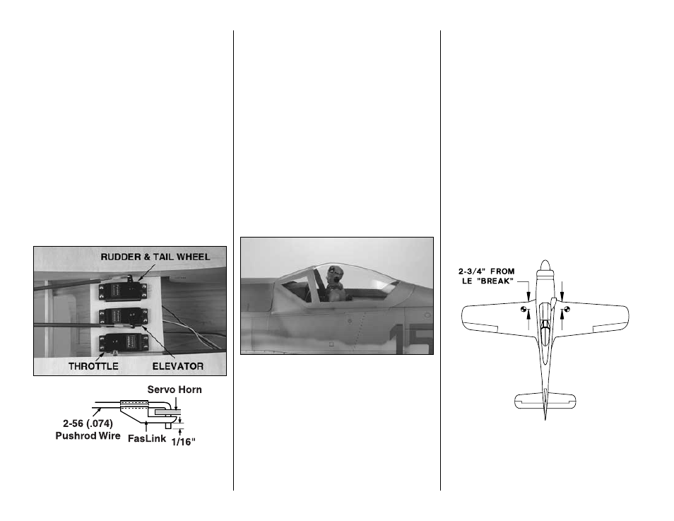
5. Install the elevator and rudder pushrods in the
fuse. Connect the pushrods to the elevator and
rudder/tail gear. With the rudder and elevators
neutral, use a felt-tip pen to mark the pushrods
where they cross the holes in the servo arms. Make
a 90-degree bend in the wires at the marks you
made. Temporarily install a nylon Faslink
™
on the
wires, then cut them so that about 1/16" protrudes
from the bottom of the Faslink. Connect the pushrods
to the servos with the Faslinks. Disconnect the radio.
❏
6. Mount the flap and servo hatches in the wing
with the #2 x 3/8" flat head screws. Hookup the
ailerons and flaps with the pushrods you’ve already
made. Use a silicone retainer on all clevises.
❏
7. Mount the receiver and battery pack if you are
not waiting until checking the C.G. to determine
where to mount them.
Mount the canopy
Here’s a close-up photo of the canopy after the
model has been finished.
❏
1. If you haven’t already done so, install the
cockpit kit (if you’ve built one) and pilot.
❏
2. Position the canopy on the fuse. Use a felt-tip
pen to trace its outline onto the covering. Use a
hobby knife with a sharp #11 blade to carefully cut a
1/16" strip of covering from the fuse. Remove the
covering, exposing the bare balsa. This will allow the
canopy to be securely attached to the fuse—not just
to the covering.
❏
3. Securely glue the canopy to the fuse using
canopy glue such as J & Z Products
Z RC/56
(JOZR5007). Use rubber bands or masking tape to
hold the canopy in position until the glue dries.
GET YOUR MODEL READY TO FLY
Balance your model
NOTE: This section is VERY important and must
NOT be omitted! A model that is not properly
balanced will be unstable and possibly unflyable.
At this stage your model should be in ready-to-fly
condition with all of the systems in place including
the engine, landing gear, covering and paint, and the
radio system (less the receiver and battery pack if
you are planning to determine their location based
upon the current C.G. location).
❏
1. Accurately mark the C.G. on the top of the wing
on both sides of the fuselage. The C.G. is shown on
the plan (CG), and is located 2-3/4" back from the
leading edge
at the LE “break” in the wing at rib
W-3. This is where your model should balance for
your first flights. Later, you may wish to experiment
-57-