Top Flite TOPA0150 User Manual
Page 19
distances are not equal (if the stab is not level),
lightly trim the stab bases until you can get the stab
level.
Use caution not to change the incidence
angle of the stab. If the stab is not exactly level, but
it’s close, sometimes all it takes is shifting the weight
slightly.
Hint: Use balsa blocks of equal thickness to
level the stab. If you do this, make certain the stab is
fully contacting the stab bases.
❏
3. Stick a T-pin into the center fuse stringer above
F-1. Tie a small loop in one end of a 50" piece of non-
elastic line such as monofilament or Kevlar fishing
line. Slip the loop over the T-pin. Fold a piece of
masking tape over the string near the other end and
draw an arrow on it. Slide the tape along the string
and align the arrow with one end of the stab as
shown in the photo. Swing the string over to the
same position on the other side of the stab. Shift the
stab and slide the tape along the string until the
arrow aligns with both sides of the stab. The stab
must remain level and centered during this process.
❏
4. Mark the stab where it aligns with the fuse so it
can be realigned after you take it off.
❏
5. Remove the stab. Mix up a batch of 30-minute
epoxy. For additional strength, add Great Planes
Milled Fiberglass (GMR6165). Apply epoxy to the
stab bases and to the bottom of the stab where it
contacts the saddles. Reposition the stab and place
weights on top of it to hold it down. Confirm stab
alignment with the pin and string. Wipe away excess
epoxy and do not disturb the model until the epoxy
has fully hardened.
Refer to this photo for the following three steps.
❏
6. Use the “T-pin and straightedge” technique to
mark a centerline down the TE of the fin. After the
epoxy from the stab has fully hardened, test fit the fin
to the stab and fuse. Use a builder’s square placed
along the centerline you marked on the fin TE to
make sure the fin is vertical. Trim the fin sheeting
where necessary for a good fit to the top of the stab
and the sub stringers.
❏
7. Temporarily join the elevators to the stab with
the elevator joiner wire and the hinges. Cut round
notches in the fin sheeting to accommodate the
elevator joiner wire.
❏
8.
With the elevator joiner wire in position, glue
the fin into position with 30-minute epoxy. Before the
epoxy cures, make certain the fin is vertical and the
front of rib V-1 is centered on F-12. Do not build up a
fillet of epoxy between the fin sheeting and the stab.
Sheet the top of the fuse
By now you’ve noticed that the Focke-Wulf fuselage
has some interesting lines and curves. Unlike many
other warbirds that have either a round fuselage
(such as a Corsair) or a “slab-sided” fuselage (such
as a Mustang), the Focke-Wulf fuse features a
mixture of irregular curves and converging angles.
While this doesn’t necessarily make sheeting the
fuselage difficult, careful thought and planning were
required during the construction of our prototype to
determine a procedure that modelers could
duplicate. Blocks are used in areas where it would be
too difficult to sheet. If you are an expert at sheeting
models, or if you prefer to do it a different way, you
could venture off.
For most modelers, we
recommend that you carefully follow these
instructions to end up with a fuselage that replicates
the lines of the Focke-Wulf.
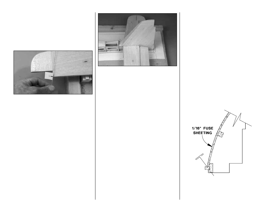
❏
1. One at a time, remove the T-pins from the main
stringer and reinsert them as shown in the sketch.
This way, the pins won’t be concealed under the
sheeting when it’s time to take the fuse off the
building board.
-19-