Top Flite TOPA0150 User Manual
Page 17
the bevel on the front of the aft stringers to the correct
angle (if you cut the stringers a few inches longer than
required you will have enough material to make a few
adjustments until you get the angle just right).
❏
4. Use a razor saw to cut partway through the
inside edges of the aft main stringers at F-12 so they
can make the bend. Pin the stringers into position
and glue them to the forward stringers. Add a few
drops of medium CA to the stringers where you cut
them at F-12.
Now for some of the fun stuff...
Note: All the following parts are die-cut 1/8" plywood
unless otherwise indicated.
❏
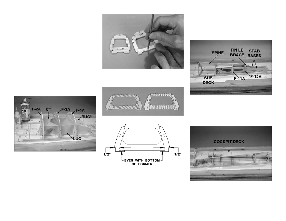
5. Without using any glue, join the parts of the
upper crutch assembly including the
left and right
upper crutches (LUC, RUC), the crutch top (CT)
and
F- 2A, F-3A and F-4A. Fit the assembly to the
main stringers over their location on the plan.
❏
6. Glue the assembly together and to the main
stringers. Use a small builder’s square to make
certain the formers are perpendicular to the building
board.
Note: Don’t worry about glue joints you can’t
reach while the fuse top is pinned to the building
board. We’ll remind you to reinforce them later.
❏
7. Use a 3/16" brass tube sharpened at the end to
cut holes centered over the punchmarks in die-cut
1/8" balsa formers
F-11A and F-10A.
❏
8. If you are going to install the optional Top Flite
Scale Cockpit kit, use a straightedge and a ballpoint
pen to mark the cut-out lines on both die-cut 1/8"
plywood formers
F-6D and F-7A as shown. The
shaded portions shown in the photo will be removed
later to accommodate the cockpit kit. Cut partway
through the formers, so they will be easier to cutout
after they are glued into position.
❏
9. Glue formers
F-5A through F-10A to the main
stringers over their location on the plan. Make certain
the formers are facing forward and use a builder’s
square to hold the formers perpendicular while
gluing them in place.
❏
10. Assemble the stab base assembly at the back
of the fuselage with both
stab bases (SB), the fin
LE brace, the die-cut 1/8" balsa formers F-11A & F-
12A, the die-cut 3/32" balsa sub deck and the die-
cut 1/8" balsa
spine. Glue the pieces into position.
❏
11. Glue together both halves of the die-cut 1/8"
balsa
cockpit deck so the notches align. Sand the
pieces flat and even. If you are going to install the
scale cockpit interior, cut the deck along the partially
embossed lines and remove that section. Fit, then
glue the cockpit deck into position.
-17-