Top Flite TOPA0910 User Manual
Page 9
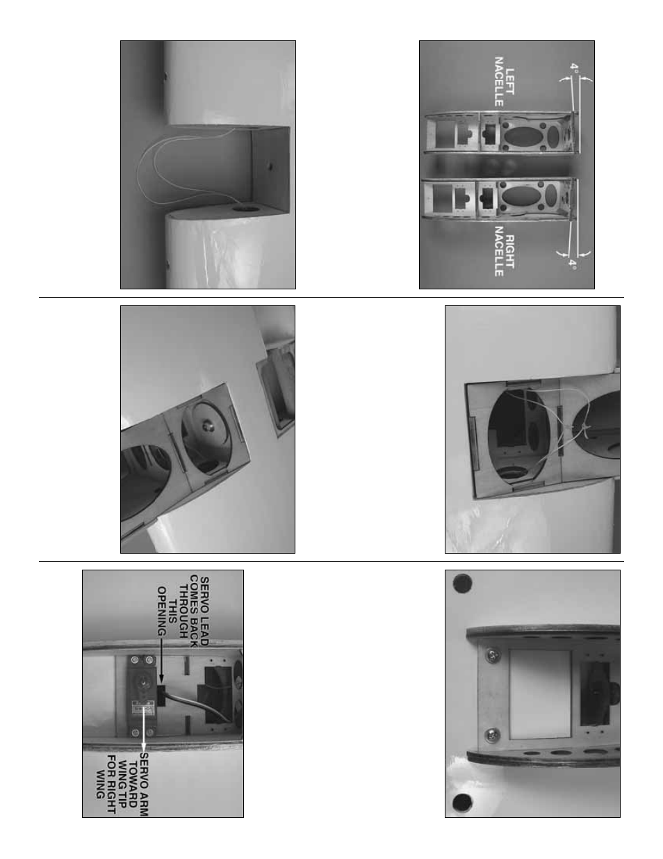
Mount the Pl
yw
ood Engine Nacelles
❏
1.
Remo
v
e
the top plate and fuel tank from the
pl
yw
ood engine nacelle
.
Set the tw
o plyw
ood
engine nacelles on y
our w
o
rkbench as sho
wn in the
photog
raph.
Looking at the top of the nacelle y
o
u
m
ust
note the diff
erence in the angle of the fire
w
a
ll
of each nacelle
.
Each nacelle has 4° of outw
ard
thr
ust b
uilt into it.
W
rite the w
ord
“left”
and
“r
ight”
on
each nacelle so y
ou can easily identify each one
.
❏❏
2.
The wing has str
ings r
unning through it f
o
r
pulling ser
vo
leads through the wing.
The str
ing is taped
at the root r
ib
, the wing tip and inside the aileron ser
vo
compar
tment.
Remo
ve
the tape and pull the e
xcess
str
ing into the front of the wing where the nacelle will be
mounted.
Re-tape the end of the str
ing to the r
ib
.
❏❏
3.
Cut the str
ings
.
Begin sliding the r
ight nacelle
in place and at the same time f
eed the str
ing through
the holes in each side of the nacelle
.
Re-tie the
str
ings
.
Apply a drop of thin CA to the knot to pre
v
ent
it from coming apar
t.
❏❏
4.
Slide the nacelle completely into the wing.
Attach the nacelle to the wing with an 8-32 x 1"
[25mm] soc
k
et head cap scre
w
, a #8 loc
k w
asher
and a #8 flat w
asher
.
Apply a couple of drops of
thread loc
k
er onto the bolt bef
ore tightening the bolt
to the wing and nacelle
.
❏❏
5.
Dr
ill 3/32" [2.4mm] holes through each of the
tw
o pilot holes located at the bac
k of the nacelle
.
D
rill
through the nacelle and into the hardw
ood b
loc
k
located in the wing.
Inser
t and remo
v
e a #6 x 1/2"
[13mm] scre
w into each of the holes
.
Apply a couple
drops of thin CA into the holes to harden the threads
.
Once the glue has cured install the #6 scre
ws and #6
flat w
ashers into each of the holes
.
❏
6.
Repeat steps 1- 5 f
or the left wing panel.
Install Flap,
Thr
ottle and Ailer
on
Ser
v
os and Pushr
ods
❏❏
1.
Install the flap ser
vo
into the rear ser
vo
opening.
Inser
t and remo
ve
a ser
vo
mounting scre
w into each of
the pre-dr
illed holes
.
Apply a couple drops of thin CA
- 9
-