Top Flite TOPA0910 User Manual
Page 20
❏
4.
Cut the 39" [990mm] pull-pull wire in half
.
Slip a
cr
imp connector onto one of the wires
.
W
rap the wire
around each of the ball links on the nose gear steer
ing.
Pull the wires tight and squeez
e the cr
imp connector
.
Inser
t the opposite end of the wire into the plastic tube
.
❏
5.
Install a 2-56 n
ut and cle
vis onto tw
o threaded
br
ass couplers
.Install the cle
vis onto the outer holes of
the ser
vo
ar
m.
Slide a cr
imp connector onto the wire
.
Then, f
eed the wire through the hole in the side of the
br
ass coupler and bac
k through the cr
imp connector
.
Do this f
or both of the wires
.
Pull the wires
, making
them equal in tension and making sure the r
udder is
centered.
Cr
imp the connectors against the wire
.
❏
6.
Apply thread loc
k
er to tw
o of the wheel collar set
scre
ws
.
Inser
t the scre
ws into tw
o wheel collars
.
Slide a wheel collar onto the nose gear wire
,
tightening it against the inner most flat spot on the
nose gear wire
.
Install the nose wheel onto the axle
follo
w
ed b
y
another wheel collar
, tightening it against
the remaining flat spot on the wire
.
Decision y
ou m
ust make…
Included in the kit is a fiberglass door that fits the
opening in the fuselage f
or the landing gear
.
If y
o
u
are planning to only fly this air
plane with fix
ed
landing gear
, then y
ou might wish to proceed with
step 7.
If y
ou think y
ou might be installing retr
acts at
some time in the future
, y
ou should skip step 7 and
mo
v
e
onto the main landing gear
.
The procedure
outlined in step 7 ma
y be skipped with no eff
ect on
the flying perf
or
mance of the air
p
lane
.
❏
7.
Y
ou might wish to close off the nose gear
compar
tment to minimiz
e
dr
ag to the aircr
aft.
If so
,
tr
im the door as sho
wn and glue it per
manently in
place on the fuselage
.
Main Gear
Decision y
ou m
ust make…
Look closely at the bottom of the r
ight wing.
Adjacent
to the mounting r
ails f
or the landing gear y
ou will find
the wheel opening f
or the retr
acts is co
v
e
red with
Monok
ote
.
This co
v
e
ring can be left in place to
minimiz
e
dr
ag.
If y
ou are interested in a more scale
lik
e appear
ance
, y
ou might wish to per
manently
mount the fiberglass gear doors as sho
wn in the
fo
llo
wing instr
uctions
.
If there is a chance that y
o
u
might install retr
acts in the future
, it is recommended
that y
ou lea
v
e the co
v
e
ring in place and not install
the gear doors
.
If y
ou choose to lea
v
e
the co
v
e
ring in
place skip ahead to step 3.
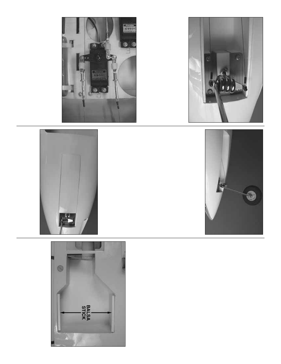
❏❏
1.
Cut the co
v
e
ring from the wheel w
ells
.
F
rom
the 1/8" x 3/16" x 15-1/2" [3mm x 5mm x 390mm]
white balsa stic
k, cut f
our 3" [76mm] stic
ks
.
G
lue tw
o
into each wheel w
ell to suppor
t the door when it is
glued in place
.
P
osition the stic
ks 1/8" [3mm] abo
v
e
the bottom skin of the wing.
- 20
-