Retra ct able landing gear – Top Flite TOPA0910 User Manual
Page 22
RETRA
CT
ABLE LANDING GEAR
The f
o
llo
wing instr
uctions will tak
e y
ou through the
installation of the retr
actab
le landing gear
.T
o maximiz
e
the scale appear
ance of the air
plane w
e
ha
ve
included
landing gear doors f
o
r the nose gear and the main gear
.
These doors are intended f
o
r use with the installation of
the fix
ed landing gear
.
Though w
e
are not pro
viding
instr
uctions f
or their use on retr
actab
le landing gear
, the
more
“scale-minded”
pilot might wish to use them and
create their o
wn door hinging and closure mechanisms
.
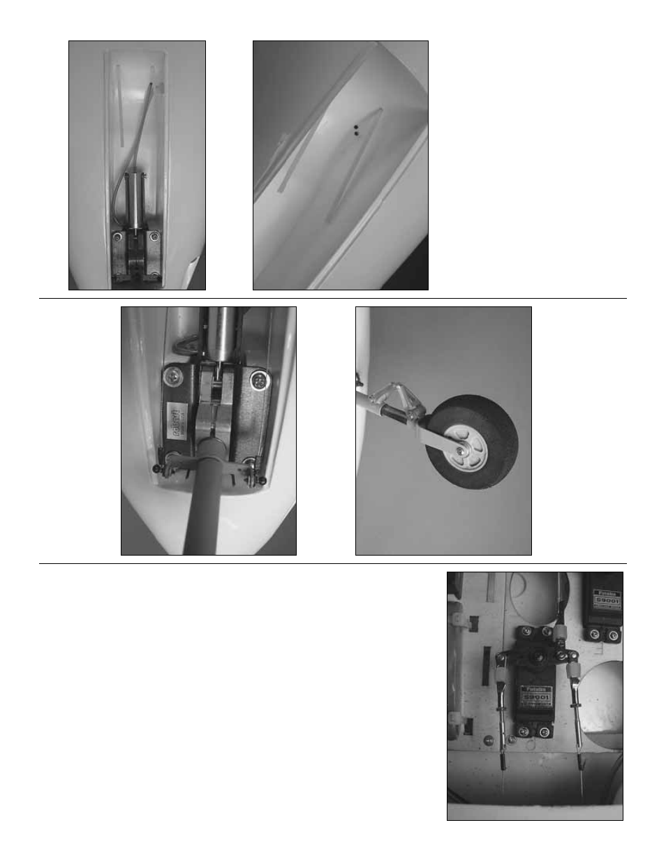
Nose Gear
❏
1.
Dr
ill tw
o 1/8" [3mm] holes in the cor
ner of the
nose gear wheel w
e
ll f
or the air lines
.
❏
2.
Install 18" [460mm] of air line onto each air inlet
on the landing gear
.
F
eed each line into the holes y
o
u
dr
illed, pulling the lines into the r
adio compar
tment.
Place the nose gear onto the mounting r
a
ils
.
M
ar
k the
hole locations and then dr
ill a 7/64" [2.8mm] hole on
each of the mar
ks
.
Install the nose gear assemb
ly
with f
our #6 x 1/2" [13mm] machine scre
ws
, #6 flat
w
ashers and #6 loc
k w
ashers
.
❏
3.
Install the nose wheel.
Use tw
o #8 flat w
ashers on
each side of the wheel to k
eep it centered in the f
o
rk
.
❏
4.
Cut the 39" [990mm] pull-pull wire in half
.
Slip a
cr
imp connector onto one of the wires
.W
rap the wire
around each of the ball links on the nose gear
steer
ing.
Pull the wires tight and squeez
e the cr
imp
connector
.
Inser
t the opposite end of the wire into the
plastic tube
.
❏
5.
Install a 2-56 n
ut and cle
vis onto tw
o threaded
br
ass couplers
.
Install the cle
vis onto the outer holes
of the ser
v
o
ar
m.
Slide a cr
imp connector onto the
wire
.T
hen, f
eed the wire through the hole in the side
of the br
ass coupler and bac
k through the cr
imp
connector
.
Do this f
or both of the wires
.
Pull the
wires
, making them equal in tension and making
sure the r
udder is centered.
Cr
imp the connectors
against the wire
.
- 22
-