Final assembl y – Top Flite TOPA0910 User Manual
Page 26
❏
4.
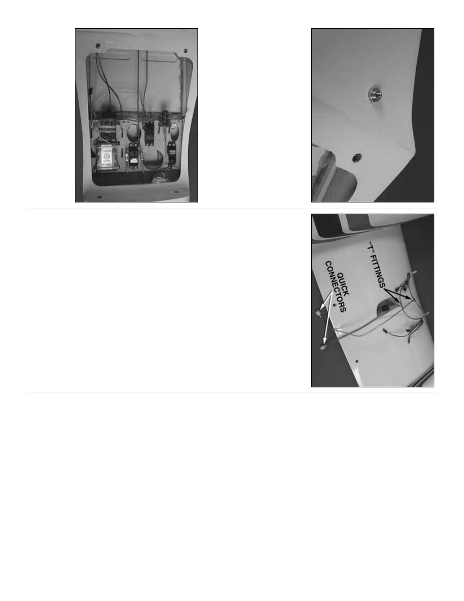
Decide on a location to mount the air fill v
alv
e
.
W
e
mounted ours on the bottom of the fuselage just
behind the tr
ailing edge of the wing.
This k
eeps the
v
alv
e some
what hidden b
ut it is not the most easily
accessib
le location.
If y
ou do not mind it being visib
le
y
ou ma
y wish to locate in on the fuselage in a place
more con
v
enient f
or filling the air tank.
❏
5.
Install the air lines to the air tank, fill v
alv
e and
air control v
alv
e as sho
wn in the instr
uctions that
came with the air control kit.
Install the connectors
that will connect the air
lines from the main gear to
the air
lines in the fuselage
.
❏
6.
Y
ou no
w ha
v
e
to mak
e
a couple of decisions
regarding the wing.
The wing is designed in tw
o pieces
fo
r easier tr
anspor
tation and stor
age
.
Those of y
o
u
that ha
v
e
an appropr
iately siz
ed v
ehicle and adequate
stor
age area ma
y wish to lea
v
e
the wing assemb
led in
one piece
.
If y
ou will be lea
ving the wing together
, join
the tw
o air lines that will retr
act the landing gear with
a
“T”
fitting.
Join the remaining tw
o lines with another
“T”
fitting.
Install a 12" [310mm] length of air line onto
the
“T”
fitting and an air line quic
k connector on the
other end.
If y
ou will be taking y
our wings apar
t,
substitute a pair of quic
k connectors f
or the
“T”
fittings
.
FINAL ASSEMBL
Y
Completing the Radio Installation
❏
1.
Connect the ele
v
a
tor and r
udder ser
v
os to the
receiv
er
.
If y
ou ha
v
e
installed retr
acts
, connect the
retr
act ser
v
o
to the receiv
er too
.
❏
2.
Y
ou ha
v
e
a f
e
w options when connecting the
aileron, flap and throttle ser
v
o
s
.
Depending on the
n
umber of channels y
ou ha
v
e
a
v
ailab
le on y
our r
adio
system, y
ou ma
y wish to ha
v
e
each ser
v
o
lead plug
into its o
wn receiv
er slot.
If y
ou choose to do this
follo
w the instr
uctions included with y
our r
adio
system.
The option of using a
“Y”
connector is
probab
ly the simplest method.
Install a
“Y”
connector
betw
een the tw
o aileron connections coming out of
each wing and one betw
een the flap connections in
each wing.
If y
ou intend to lea
v
e
y
our wings together
,
secure the connectors together with heat shr
ink
tubing, tape or some other method.
If y
ou w
ant the
ability to separ
ate the tw
o wings
, secure the
connectors on one wing only
.
❏
3.
F
or the throttle linkage y
ou can use
“Y”
connectors the same w
a
y done f
or the ailerons and
flaps
.
Again, if y
our r
adio has the ability to plug each
throttle ser
v
o
into its o
wn slot, y
ou might w
a
nt to
consider doing this
.
E
v
en if y
ou chose to use
“Y”
connectors on the ailerons and flaps
, y
ou might w
ant
to ha
v
e
the throttles on separ
ate channels and mix
them with the r
adio
.This w
ould giv
e y
ou the option of
star
ting and oper
ating each engine independently of
each other dur
ing the star
t up of the engines
.
❏
4.
Install a 6" [152mm] ser
v
o
e
xtension into the
slots in y
our receiv
er f
or each of the aileron, flap and
throttle ser
v
o
leads
.
This will mak
e plugging the
connections in the wing to the receiv
er easier
.
❏
5.
Install the r
adio s
witch and charge jac
k f
or y
our
par
ticular br
and of r
adio and plug it into the receiv
er
.
W
e
chose to mount ours on the bottom of the
fuselage
.
F
or easier access y
ou might w
ant to
consider mounting it to the side of the fuselage
.
Connect the Lighting System
The lighting system is a nice scale option b
ut is not
required in order to fly the air
p
lane
.
If y
ou choose not
to use the lights y
ou can skip this section of the
man
ual.
Do not operate the lighting system fr
om
the receiver batter
y
pac
k!
The lighting system will
require the use of a separ
ate 500 mAh batter
y
pac
k
and a s
w
itch har
ness f
or installation.
- 26
-