Prep ara tions, Assemble the fusela ge st and, Assemble the wing – Top Flite TOPA0910 User Manual
Page 7
- 7
-
PREP
ARA
TIONS
❏
1.
If y
o
u ha
v
e
not done so already
, remo
v
e
the
major par
ts of the kit from the bo
x and inspect f
o
r
damage
.
If an
y par
ts are damaged or missing,
contact Product Suppor
t at the address or telephone
n
umber listed in the
“Order
ing Replacement P
a
rts”
section on page 5.
❏
2.
Remo
v
e
the tape and separ
ate the ailerons and
flaps from the wing and the ele
v
ators from the stab
.
Use a co
v
e
ring iron with a co
v
e
ring soc
k on high heat
to tighten the co
v
e
ring if necessar
y.
Apply pressure
o
v
er sheeted areas to
thor
oughl
y
bond the co
v
e
ring
to the w
ood.
ASSEMBLE
THE FUSELA
GE ST
AND
Y
our kit includes a stand that can be used dur
ing the
assemb
ly process and as a useful tool f
or tr
anspor
ting
the air
plane to the field as w
ell as assemb
ly of the
air
plane at the field.
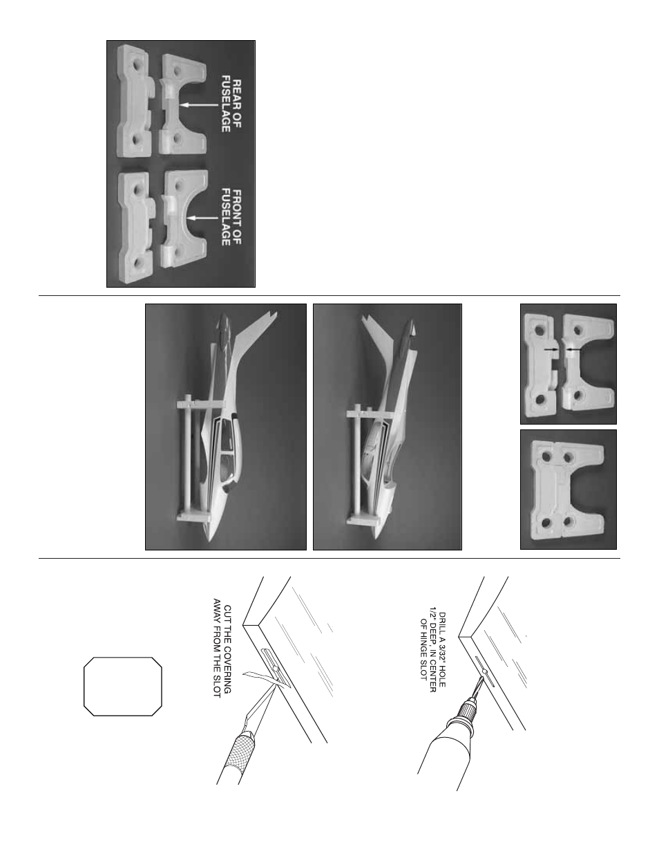
❏
1.
The stand consists of f
our f
oam cr
adle
components and tw
o PVC tubes
.
There are tw
o
diff
erent cutouts in the cr
adle
.The cur
v
ed section fits
the front of the fuselage while the one that has the
flat cut fits the rear half of the fuselage
.
❏
2.
The top and bottom stand components will fit
sn
ugly together
.
F
it the bottom with the top cr
adle
(the one with the flat cut) as sho
wn.
❏
3.
When placed into the cr
adle upside do
wn the
fuselage is ele
vated so the tail and the cabin top are off
of y
our w
o
rk
bench.
Y
ou can also place the fuselage
upr
ight in the cr
adle
.If y
ou install the fix
ed landing gear
and wish to tr
anspor
t the fuselage or w
o
rk
on it on y
our
w
o
rkbench, y
ou will w
ant to place the other bottom
cr
adle component onto the front cr
adle
.
This will allo
w
enough clear
ance f
or the nose gear
.
ASSEMBLE THE
WING
Install the Ailer
o
ns and Flaps
Assemb
le the right wing fir
st so y
our
w
o
rk matc
hes the photos.
❏❏
1.
Dr
ill a 3/32" [2.4mm] hole
, 1/2" deep in the
center of each hinge slot to allo
w the CA to
“wic
k”
in.
F
o
llo
w-up with a #11 b
lade to clean out the slots
.
Hint:
If y
ou ha
v
e
one
, use a high-speed rotar
y tool to
dr
ill the holes
.
❏❏
2.
Use a shar
p #11 b
lade to cut a str
ip of
co
v
e
ring from the hinge slots in the wing and aileron.
❏❏
3.
Cut three 1" x 1" [25mm x25mm]
hing
es
from
the
CA hing
e strip
.
Snip off the cor
ners so the
y go
in easier
.