Assemble the fusela ge – Top Flite TOPA0910 User Manual
Page 15
❏
2.
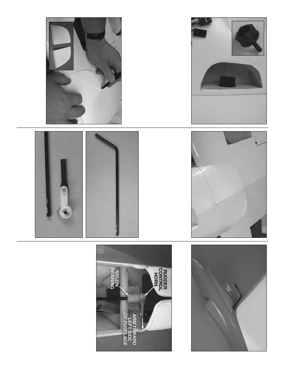
Inser
t the 1/4-20 thumbscre
w
into the opening
in the r
ight wing panel.
Tighten the scre
w
, pulling the
wings together
.
❏
3.
Place the fuselage upside do
wn into the f
oam
stand.
Install the wing onto the fuselage
, secur
ing it
with tw
o 1/4-20 n
ylon wing bolts
.
❏
4.
Locate the tw
o fiberglass wing f
air
ings
.
P
lace
them on each wing.
T
race the outline of the f
air
ing
onto the wing.
Using a shar
p modeling knif
e
, carefully
cut the co
v
e
ring from the wing.
Be careful to only cut
through the co
v
e
ring, not the surf
ace of the wing.
❏
5.
Glue the f
air
ings to the wing.
After the glue has
cured, remo
v
e
the wing from the fuselage and
separ
ate the tw
o halv
es of the wing.
ASSEMBLE THE
FUSELA
GE
Install the Ele
v
ator and Rud
der
❏
1.
Locate the r
udder control wire and the r
udder
control hor
n.
Note that the wire has a flat spot pre-cut
in the end of the wire
.
❏
2.
Slip the r
udder control wire into the hole in the
top of the fuselage
.
❏
3.
Put a 4-40 n
ut onto a 4-40 x 36" [914mm] wire
pushrod.
Scre
w the wire pushrod into the n
ylon s
w
iv
el
connector appro
ximately 20 tur
ns
.
Loc
k the n
u
t
against the connector
.
F
rom the bac
k of the fuselage
,
slide the pushrod wire into the center plastic guide
tube that is pre-installed in the fuselage
.
S
lide the
rudder control wire through the n
ylon bear
ing.
Place
the r
udder control hor
n onto the r
udder control wire
.
When installing it o
v
er the wire be sure the control
ar
m is on the left side of the fuselage
.R
emo
v
e the set
scre
w from the control hor
n and apply a couple of
drops of thread loc
k
er to the threads
.
Re-inser
t the
scre
w into the control hor
n, tightening the set scre
w
against the flat spot on the r
udder control wire
.
- 15
-