Top Flite TOPA0910 User Manual
Page 10
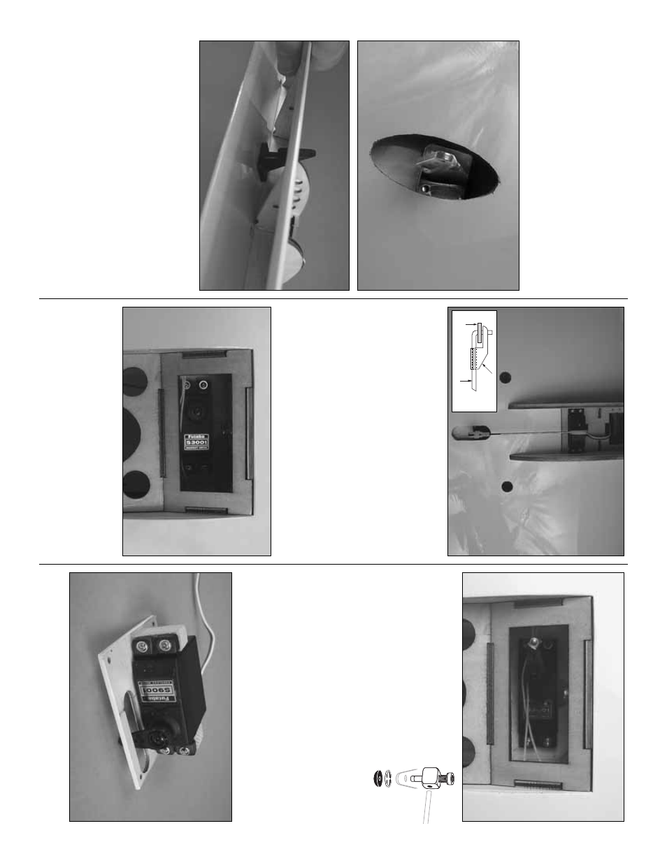
into the holes to harden the threads
.Once the glue has
cured re-install the ser
vo
mounting scre
ws
.
Be sure the
ser
vo
lead comes up through the slot alongside of the
ser
vo
.
When installing the flap ser
vo
in the r
ight wing
panel, the ser
vo ar
m should be pointed to
w
ards the
wing tip
.
When installing the ser
vo
in the left wing, the
ar
m should be pointed to
w
a
rds the wing center
.
❏❏
2.
Center a b
lac
k control hor
n in the opening
abo
ve the flap
, positioning it as sho
wn (the control hor
n
should be bac
kw
ards from what w
ould be considered
the nor
mal direction of a control hor
n.) Dr
ill a 1/16"
[1.6mm] hole through each of the mounting holes in the
control hor
n and into the plyw
ood plate in the flap
.
D
rill
only through the plyw
ood plate
.
DO NO
T
dr
ill through
the flap
.
Inser
t and remo
ve
a #2 x 3/8" [10mm] scre
w
into each of the holes
.
Apply a couple drops of thin CA
into the holes to harden the threads
.Once the glue has
cured attach the hor
n
to the flap with f
our
#2 x 3/8" [10mm] scre
ws
.
❏❏
3.
Scre
w
a n
ylon cle
vis onto a .074 x 6" [152mm]
threaded wire 20 tur
n
s
.
Slide a n
ylon cle
vis retainer
onto the cle
vis
.
Install the cle
vis into the outer
most
hole of the control hor
n.
Then slide the silicone
retainer o
v
er the cle
vis
.
D
rill a 5/64" [2mm] hole in the
outer hole of the ser
v
o
ar
m.
P
osition the ser
v
o
ar
m as
sho
wn and be sure the flap is fully closed.
With a fine
tip mar
k
er
, mar
k the wire where it aligns with the outer
hole of the ser
v
o
ar
m.
Mak
e a 90 deg
ree bend on the
mar
k.
Cut the wire so the wire is 3/8" [10mm] in length
after the bend.
Inser
t the wire into the ser
v
o
ar
m and
loc
k it in place with a n
y
lon F
aslink.
❏❏
4.
Install the throttle ser
vo
into the ser
vo
opening.
(Note that the ser
vo
is mounted on the bottom of the
nacelle).
Inser
t and remo
ve
a ser
vo
mounting scre
w into
each of the pre-dr
illed holes
.Apply a couple drops of thin
CA into the holes to harden the threads
.
Once the glue
has cured, re-install the ser
vo
mounting scre
ws
.
❏❏
5.
Install a br
ass scre
w loc
k
connector
, n
y
lon retainer r
ing and a
4-40 x 1/4" [6mm] soc
k
et head cap
scre
w onto the ser
v
o
ar
m.
Then
center the ser
v
o
and install the ar
m
onto the ser
v
o
.
❏❏
6.
Install a 6" [152mm] ser
v
o
e
xtension onto the
throttle and flap ser
v
o
leads
.
Secure the e
xtension to
the lead with tape
, a piece of shr
ink tube or some
other method to k
eep them from coming unplugged.
❏❏
7.
Install a 24" [610mm] ser
v
o
e
xtension onto
the aileron ser
v
o
lead.
Secure the e
xtension to the
lead with tape
, a piece of shr
ink tube or some other
method to k
eep them from coming unplugged.
❏❏
8.
Install the aileron ser
v
o
betw
een the w
ooden
ra
ils under the
ailer
on ser
v
o
co
ver
using the
- 10
-
FA
S
LINK
2-56 (.074")
PU
S
HR
OD WIRE
S
ER
V
O
HORN