Top Flite TOPA0910 User Manual
Page 28
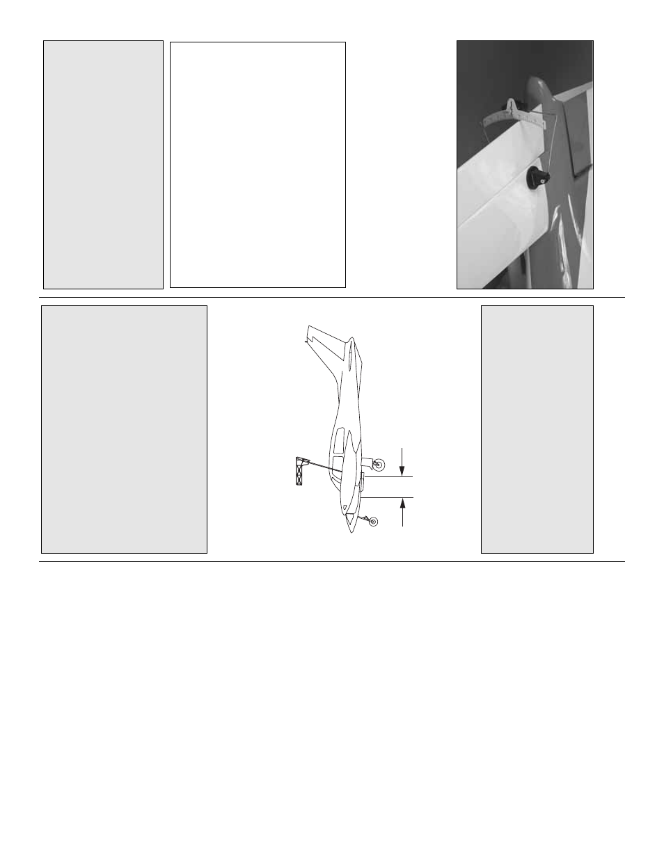
Set the Contr
ol
Thr
o
w
s
Use a Great Planes AccuThro
w
™
(or a r
uler) to
accur
ately measure and set the control thro
w of each
control surf
ace as indicated in the char
t that f
o
llo
ws
.
If
y
our r
adio does not ha
v
e
dual r
a
tes
, w
e
recommend
setting the thro
ws at the high r
a
te setting.
NO
TE:
The
thro
ws are measured at the
widest par
t
of the
ele
v
ators
, r
udder and ailerons
.
Balance the Model (C.G.)
At this stage the model should be in ready-to-fly
condition with all of the systems in place including
the engines
, landing gear and the r
adio system.
❏
1.
Use a f
e
lt-tip pen or 1/8" [3mm]-wide tape to
accur
ately mar
k the C
.G.
on the top of the wing on
both sides of the fuselage
.The C
.G.
is located 3-7/16"
[87mm] bac
k from the leading edge of the wing at the
fuselage sides
.
❏
2.
With the wing attached to the fuselage
, all par
ts
of the model installed (ready to fly) and an empty fuel
tank, place the model upsidedo
wn on a Great Planes
CG Machine
™
, or lift it upside do
wn at the balance
point y
ou mar
k
ed.
❏
3.
If the tail drops
, the model is
“tail hea
vy”
and the
batter
y
pac
k and/or receiv
er m
ust be shifted f
orw
ard
or w
e
ight m
ust be added to the nose to balance
.If the
nose drops
, the model is
“nose hea
vy”
and the batter
y
pac
k and/or receiv
er m
ust be shifted aft or w
eight
m
ust be added to the tail to balance
.
If possib
le
,
relocate the batter
y pac
k or eliminate an
y additional
ballast required.
Use Great Planes (GPMQ4485)
“stic
k on”
lead.
A good place to add stic
k-on nose
w
eight is in the nose of the fuselage
.
Begin b
y
placing
incrementally increasing amounts of w
eight on the
inside of the fuse until the model balances
.
O
nce y
o
u
ha
v
e
deter
mined the amount of w
eight required, it
can be per
manently attached.
If required, tail w
eight
ma
y be added inside the rear of the fuselage
.
❏
4.
IMPOR
T
ANT
:
If y
ou f
ound it necessar
y to add
an
y w
eight, rechec
k the C
.G.
after the w
eight has
been installed.
Balance the Model Laterall
y
❏
1.
With the wing le
v
e
l, ha
v
e
an assistant help y
o
u
lift the model at the tip of the nose and the tail.
D
o
this se
v
e
ra
l times
.
❏
2.
If one wing alw
a
ys drops when y
ou lift the model,
it means that side is hea
vy
.
B
alance the air
plane b
y
adding w
eight to the other wing tip
.
An airplane that
has been laterall
y balanced will trac
k better in
loops and other maneuver
s.
This is where y
our model should balance f
or the first
flights
.
Later
, y
ou ma
y wish to e
xper
iment b
y
shifting
the C
.G.
up to 5/16" [8mm] f
orw
ard or 5/16" [8mm]
bac
k
to change the flying char
acter
istics
.
M
o
v
ing the
C
.G.
forw
ard ma
y impro
ve
the smoothness and
stability
, b
ut the model ma
y then require more speed
for tak
eoff and mak
e
it more difficult to slo
w
f
o
r
landing.
Mo
ving the C
.G.
aft mak
es the model more
maneuv
er
ab
le
, b
u
t could also cause it to become too
difficult to control.
In an
y case
,
star
t at the
recommended balance point
and do not at an
y
time balance the model outside the specified r
ange
.
3-7/16" [87mm]
More than an
y other f
actor
, the C
.G.
(balance
point) can ha
v
e
the
greatest
eff
ect on ho
w a model
flies
, and ma
y deter
mine whether or not y
our first
flight will be successful.
If y
ou v
alue this model and
wish to enjo
y
it f
or man
y flights
,
DO NO
T
O
VERLOOK
THIS IMPOR
T
ANT PR
OCEDURE.
A
model that is not proper
ly balanced will be
unstab
le and possib
ly unfly
ab
le
.
IMPOR
T
ANT
:
The Cessna 310 has been
e
x
tensivel
y
flo
wn and tested to arr
iv
e at the thro
ws at which it flies
best.
Flying y
our model at these thro
ws will pro
vide
you with the g
reatest chance f
or successful first flights
.
If
, after y
ou ha
ve
become accustomed to the w
a
y the
Cessna 310 flies
, y
o
u w
ould lik
e to change the thro
ws
to suit y
our taste
, that is fine
.
H
o
w
e
ver
, too m
uch
control thro
w could mak
e the model difficult to control,
so remember
, “more is not alw
a
ys better
.”
These are the recommended control surf
ace thro
ws:
High Rate
Lo
w Rate
ELEV
A
T
OR
1" up
3/4" up
1" do
wn
3/4" do
wn
[25mm]
[19mm]
R
UDDER
1-1/2" r
ight
1" r
ight
1-1/2" left
1" left
[38mm]
[25mm]
AILER
ONS:
3/4" up
1/2" up
3/4" do
wn
1/2" do
wn
[19mm]
[19mm]
FLAPS:
1-5/8" [40mm] do
wn
- 28
-