Top Flite TOPA0910 User Manual
Page 13
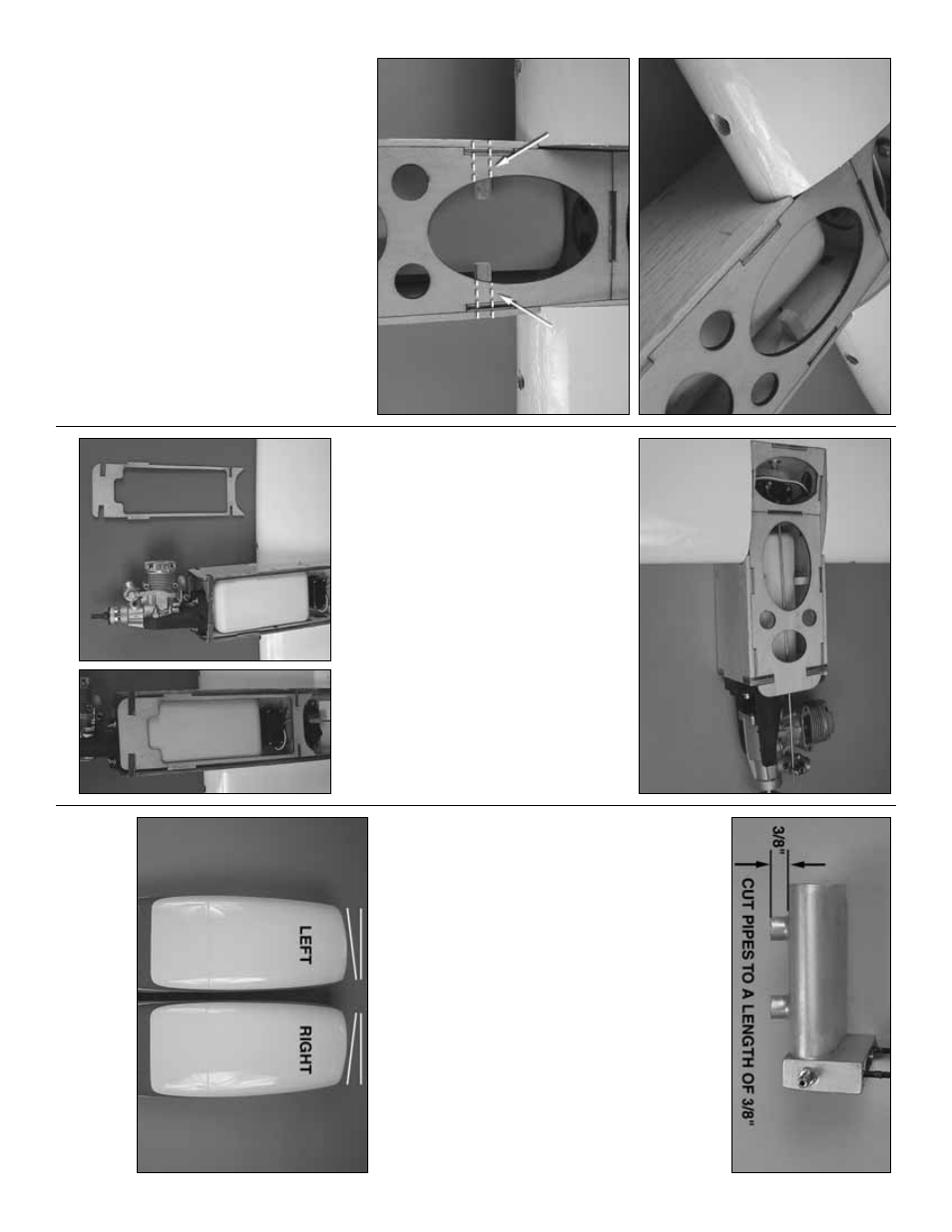
❏❏
5.
F
rom one of the 1/4" x 1/4" x 12" [6mm x 6mm
x 305mm] balsa stic
ks
, cut tw
o stic
ks to a length of 1"
[25mm].
Inser
t them into the square openings on each
side of the bottom of the nacelle
.
Mak
e sure the
y
e
xtend into the nacelle f
ar enough to suppor
t the fuel
tank.
Then, glue them in place
.
❏❏
6.
Install silicone fuel tubing onto the alumin
um
tubes from the fuel tank.
The line with the fuel clunk
will f
eed to the fuel inlet at the needle v
alv
e and the
other will attach to the pressure tap on the m
uffler
.
If
y
ou choose to use some kind of an e
xter
nal fuel
v
alv
e
, f
o
llo
w
the instr
uctions with y
our par
ticular
br
and of fuel v
alv
e
.Y
ou can also install a third line to
the tank and use it f
or filling the tank.
The method y
o
u
use is y
our choice b
ut mak
e
y
our decision bef
ore
mo
ving onto the installation of the fuel tank.
❏❏
7 Install a br
ass scre
w loc
k
connector
, n
ylon
retainer r
ing and a 4-40 x 1/4" [6mm] soc
k
e
t head cap
scre
w
onto the throttle ar
m on the engine
.
Cut the
threaded por
tion off of a 2-56 x 12" [305mm] pushrod
wire
.
S
lide the wire through the scre
w loc
k
connector
on the throttle ar
m, pushing it bac
k to
w
a
rds the throttle
ser
v
o
.
Bend the wire as needed to clear the top of the
fuel tank and reach the scre
w loc
k
connector
.T
ighten
the set scre
ws against the wire pushrod.
❏❏
8.
Epo
xy the top of the nacelle in place
.
A note about the m
u
ffler:
A wide v
a
riety of m
ufflers
are a
vailab
le
.
On our O
.S .46 w
e
used the Bison
m
uffler (BISG4046) and cut the pipes to a length of
3/8" [10mm].
This allo
w
ed the co
wl to slip o
ver the
engine and m
uffler y
e
t still allo
ws the e
xhaust to clear
the inside of the nacelle
.
C
ut the pipes as sho
wn.
Lea
ve
the m
uffler off the engine f
o
r no
w
.
This will
mak
e
the installation of the
fiber
glass nacelle
easier
.
❏
9.
Repeat steps 1- 8 f
or the left wing panel.
Install Fiber
glass Nacelle
❏❏
1.
Glue tw
o of the 1/4 x 1-1/8" [6mm x 30mm]
n
ylon do
wels
into the leading edge of the wing on
each side of the nacelle with epo
xy
.
The do
w
els
should e
xtend from the leading edge of the wing
appro
ximately1/2" [13mm].
❏❏
2.
Place the tw
o nacelles side b
y
side
.
Each
ha
v
e
outboard thr
ust angles b
u
ilt into the front of the
nacelle
.
Identify the r
ight and left and mar
k this on
the inside of the nacelle
.
- 13
-