Top Flite TOPA0704 User Manual
Page 6
6
PREPARATIONS
❏
1. If you have not done so already, remove the major
parts of the kit from the box and inspect for damage.
If any parts are damaged or missing, contact Product
Support at the address or telephone number listed in
the “Kit Inspection” section on page 5.
❏
2. Use a covering iron with a covering sock on high
heat to tighten the covering if necessary. Do this for all
of the components of the model. Apply pressure over
sheeted areas to
thoroughly
bond the covering to the
wood. Refer to the separate instruction sheet titled
How To Tighten Covering On ARF Models
. Follow the
instructions to tighten the covering. If you prefer to get
started on assembly right away, the tightening process
could be done later (but it is usually easiest to do while
the model is still in separate pieces).
❏
3. Pull on all control surfaces to be sure all hinges
are securely glued in place.
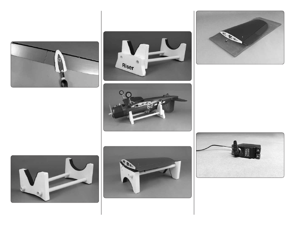
AIRPLANE STAND AND PROTECTIVE PAD
Your kit includes a foam stand and a protective pad to
help prevent “hangar rash” during the assembly process.
The foam stand is also a great aid when installing the
wing to the fuselage at the airfi eld. To assemble the
stand, slide the two plastic tubes into the foam cradles.
One side of the cradle fi ts the fuselage.
When the riser is added it offers protection to the fi n/
rudder from the bench.
The other side of the cradle matches the contour of the
wing, allowing the cradle to be used for a wing holder.
The foam pad can be used on your workbench to provide
cushioning for the components when working with them
on your workbench.
ASSEMBLE THE WING
Note: Throughout this instruction manual you will be
instructed to use screws to secure different parts. In
all cases, whenever a screw is threaded into wood
sheeting or wood blocks, we recommend that you install
the screw and then remove it. Apply a drop of thin CA
glue into the hole to harden the threads. After the glue
has hardened, re-install the screw. Following this step
will insure that you have a solid thread for your screws.
❏
❏
1. Begin with your right
wing panel
fi rst so your
assembly matches the photos in the manual. Cut three
arms from a servo horn, leaving a single servo arm.
The distance from the center of the arm to the outer
hole should be approximately 3/4" [19mm]. Center the
servo and install the arm as shown. Install the rubber
grommets and eyelets on the servo.