Top Flite TOPA0704 User Manual
Page 26
26
❏
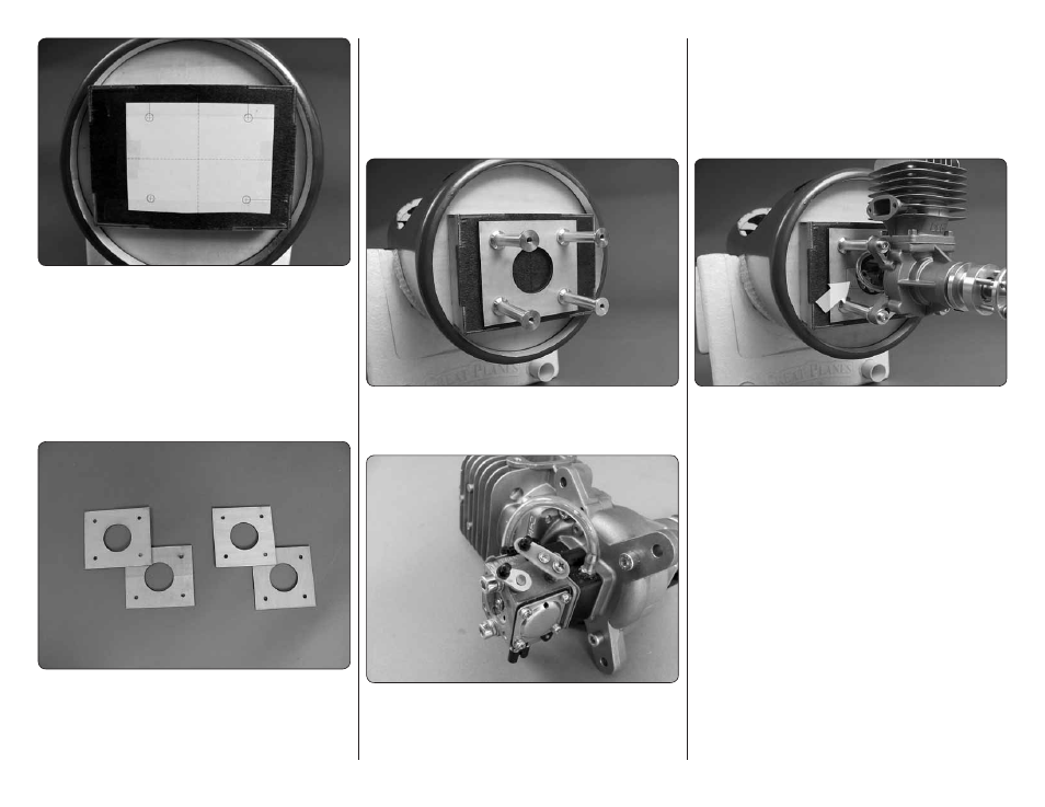
1. Cut out the paper mounting template for the DLE
55 located on page 47 of this manual. Tape the template
in place on the fi rewall, aligning the crossing lines with
the lines embossed onto the fi rewall.
❏
2. Drill a 1/16" pilot hole through the paper templates.
Remove the template from the fi rewall. Then drill 1/4"
[6mm] holes through each pilot hole. Before drilling the
holes check your particular brand of engine and the
hardware required for mounting the engine.
❏
3. We have included two pairs of four plywood spacers.
The fi rewall has been positioned so that with or without
the use of spacers nearly every engine brand can be
properly spaced from the fi rewall. Locate the spacers
that match the hole pattern for the DLE 55. You will need
to use three of these spacers. The other pattern may
be used for other brands. Install your mounting bolts
for the stand-offs into the back side of the fi rewall. (We
also recommend the use of 3/4" [19mm] fender washers
with your mounting bolts). Install the plywood spacers
over the mounting bolts.
Do not
glue the spacers to
the fi rewall.
❏
4. Hand tighten the stand-offs against the fi rewall.
Do not do the fi nal installation at this time. In the next
few steps you will be removing the engine several times.
❏
5. Install the servo arm extension onto the engine
as shown in the engine assembly instructions. Install a
2-56 ball into the hole in the end of the throttle arm and
secure it with a couple of drops of thread locker and a
2-56 nut. Do the same to the choke arm if you will be
activating the choke with a servo. (
Note: We will be
showing the installation of a servo and linkage for the
choke. We understand that many modelers have their
own way of activating the choke. If you do not wish to
use a servo to activate your choke,
skip any references
to the choke installation in the instructions that follow).
❏
6. Temporarily mount the engine to the stand-offs.
(Be sure when installing the engine that you mount it
in the inverted position on the fuselage).
Look at the
location of both the throttle and choke arms. You need
to make clearance for them in the spacers. Mark the
portion of the spacer that needs to be removed. Remove
the stand-offs and spacers, and then cut the area you
marked from both spacers.