Top Flite TOPA0704 User Manual
Page 28
28
❏
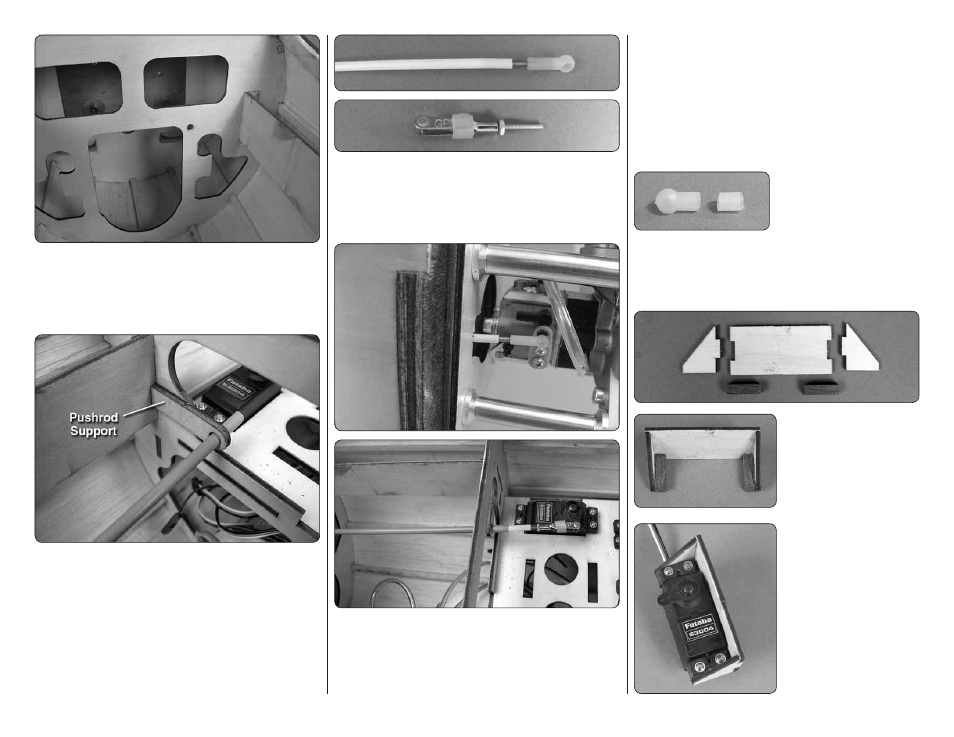
10. Locate the 12-1/2" [320mm] long tube. Insert the
tube into the hole you drilled in the fi rewall and guide it
into the fuselage. Align it with the servo arm. The tube
will run into a former. Mark the spot where it contacts
the former and drill a 3 /16" [4.8mm] hole in the former.
❏
11. Slide the tube through the hole you made in
the former, guiding it towards the throttle servo. Slide
the plywood pushrod support over the tube. Align the
tube with the outer hole in the servo arm. Then glue
the support to the former. Roughen the tube where it
passes through the fi rewall and formers before gluing
the tube in place.
❏
12. Thread the nylon ball link and threaded rod onto
the end of the inner pushrod tube. Locate another 2-56
1" [25mm] threaded rod, a metal clevis, 2-56 nut and
silicone clevis keeper. Thread the nut and clevis onto
the wire and slide the clevis keeper onto the clevis.
❏
13. Temporarily slide the inner pushrod tube into
the outer pushrod and snap the nylon ball link onto
the ball on the throttle arm. Install the clevis into the
outer hole of the throttle servo arm. Using the length
of the threaded wire in the clevis, determine where to
cut off the excess pushrod from the inner pushrod tube.
Remove the clevis and wire from the servo arm. Cut
the inner pushrod tube and then screw the threaded
wire and clevis into the tube. Re-install the clevis into
the outer hole in the servo arm.
Steps 14-21 are only if you will be installing a choke
servo. If you will not be doing this, skip ahead to
“Install
the Cowl”.
❏
14. Cut the threaded
portion of a nylon ball link in
half. Thread the cut ball link
onto a 2-56
1" [ 25 mm]
threaded rod. Snap the ball
link and wire onto the ball on the choke arm. Using the
same technique used for the throttle, mark where the
wire contacts the fi rewall. Drill a 3/16" [4.8mm] hole
through the fi rewall on the mark.
❏
15. Locate the plywood
components of the choke
servo tray and two 1/4"
1/4"
7/8" [ 6 mm
6 mm
21 mm] hardwood
blocks. Glue the servo tray
together as shown.
❏
16. Install the servo
into the servo tray using
the hardware that came
with the servo.