Top Flite TOPA0704 User Manual
Page 23
23
❏
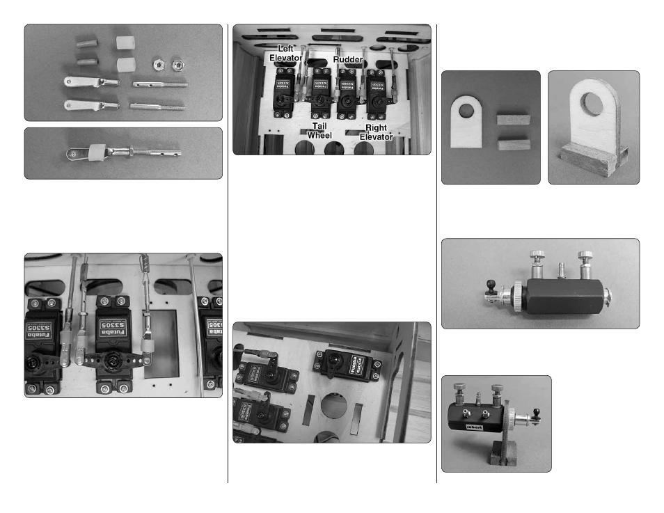
7. Locate two 2-56 threaded clevises, crimp
connectors, silicone clevis connectors, 2-56 nuts and
2-56 threaded couplers. Thread a 2-56 nut and clevis
onto the threaded coupler as well as the silicone clevis
keeper. Be sure to apply a couple of drops of thread
locker to the coupler and nut.
❏
8. Slide one of the crimp connectors onto one of the
tail wheel pull-pull wires and then insert the wire through
the bottom hole in the threaded coupler. Attach the clevis
to the control horn. Repeat this with the remaining clevis
and crimp connector. Center the servo and the tail wheel.
Use the same technique you used when you secured
the pull-pull wires to the tail wheel, pulling the wires
tight before crimping the crimp connector with a plier.
❏
9. This is how the servo installation should look. Make
sure you have put all of the clevis retainers in place and
applied thread locker to the nuts.
INSTALL THE AIR CONTROL SYSTEM
IMPORTANT:
The next step instructs you on the
installation of the air control valve servo. You will be
instructed to mount it on the right side of the fuselage.
It is mounted on the right side because our engine
installation requires the throttle servo to be on the left
side of the fuselage. Take a look at your engine and
determine which side the throttle servo needs to be
on. If you need to mount the throttle servo on the right
side you can follow the installation instructions for the
air control valve servo but install it on the left side.
❏
1. On the right side of the fuselage install the servo
that will operate the air control valve for the retractable
landing gear using the hardware that came with the
servo. From the servo horn with the shortest set of
arms, cut away the arms leaving a single servo arm.
Enlarge the outer hole in the servo arm with a 3/32"
[2.4mm] drill bit.
❏
2. Locate the plywood mounting bracket for the air
control valve and two 1/4"
1/4"
3/4" [6 mm
6 mm
19 mm] hardwood blocks. Glue the blocks onto both
sides of the bracket.
❏
3. Install an 0-80 ball and nut into the hole in the
end of the air control valve. Be sure to apply a drop of
thread locker to the threads.
❏
4. Secure the air
control valve to the
mounting bracket. Be
sure to use a couple of
drops of thread locker
on the nut.