Channel radio setup, Final hookups and checks, Set up your throttles – Top Flite TOPA0500 User Manual
Page 62
❏
2. All components should be in the model and it
should ready-to-fly but with empty fuel tanks.
❏
3. With the wing attached to the fuselage, the landing
gear extended (if you have retracts) and an empty fuel
tank, lift the model at the balance point or place it on your
C.G. Machine (shown in the sketch). If the tail drops, the
model is tail heavy and you must relocate your battery
pack or other components forward or add weight to the
nose. If the nose drops, it is nose heavy and you must
relocate your battery pack or other components aft or add
weight to the tail. In order to save weight, relocate your
battery pack and/or receiver or other components before
you add additional weight to arrive at the correct C.G. You
may install nose or tail weight by gluing lead weights
inside the fuselage where necessary.
Note: The amount of weight required will depend on the
engines you are using and how heavily or lightly you
built the tail.
FINAL HOOKUPS AND CHECKS
❏
1. Take the servo arms off your servos, turn on your
transmitter and center all the trims. Reinstall all the
servo arms and secure them with the screws.
❏
2. Double-check all the servos and make sure the
servo arms are secure and all the clevises have a
silicone retainer.
❏
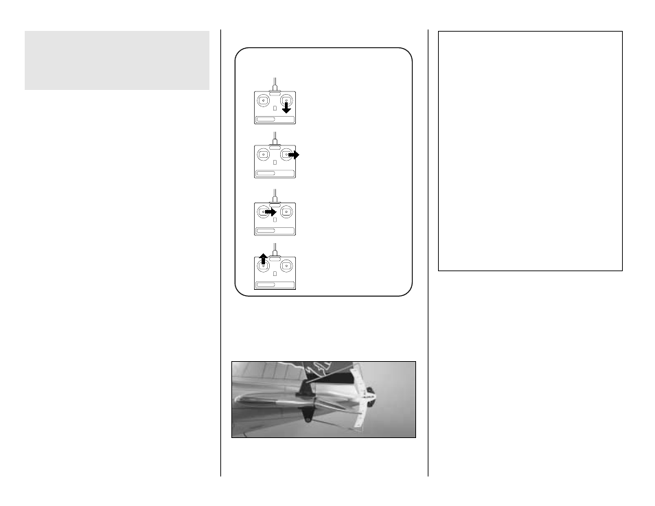
3. Make sure the control surfaces move in the proper
direction as illustrated in the following sketch.
❏
4. Adjust your pushrod hookups and set up your radio
to provide the control surface movements as follows. Use
a ruler or a Great Planes Accu Throw Control Surface
Deflection Meter (GPMR2405) to measure the throws.
The balance point and control surface throws listed
in this manual are the ones at which the DC-3 flies
best. Set up your aircraft to those specifications. If,
after a few flights, you would like to adjust the
throws or C.G. to suit your tastes, that is fine.
Too much control surface throw can make your
model difficult to control or force it into a stall, so
remember...More is not better.
SET UP YOUR THROTTLES
There are three reasons we recommend you mix your
throttle servos electronically instead of mixing them
mechanically (with a Y-connector). The first and most
important reason you should mix your throttle servos
electronically is so each engine can have its own ATV
allowing you to set the throws (idle and full throttle)
independently instead of having to adjust the linkages to
set the throws. This will make it much easier to set up
your throttles. The second reason we recommend you
mix your throttle servos electronically is so you can mount
CONTROL SURFACE THROWS
NOTE: Throws are measured at the widest part of
the control surface.
We recommend the following control surface throws:
High Rate
Low Rate
ELEVATOR: 5/8" [19mm] up
1/2" [13mm] up
5/8" [19mm] down
1/2" [13mm] down
RUDDER:
1-1/2" [38mm] right
7/8" [22mm] right
1-1/2" [38mm] left
7/8" [22mm] left
AILERONS:
5/8" [13mm] up
5/16" [8mm] up
5/8" [13mm] down
5/16" [8mm] down
FLAPS:
(Takeoff/half-flap)
1/2" [13mm]
(Landing/full-flap)
1" [25mm]
TRIM MIXING: If your transmitter has Flap to
Elevator mixing, we recommend mixing 1/16"
[1.5mm] of up elevator at half flaps and 3/32"
[2.5mm] of up elevator at full Flaps. This will keep the
nose level when you extend the flaps.
CARBURETOR WIDE OPEN
RUDDER MOVES RIGHT
LEFT AILERON MOVES DOWN
RIGHT AILERON MOVES UP
ELEVATOR MOVES UP
4-CHANNEL
TRANSMITTER
(STANDARD MODE 2)
4-CHANNEL RADIO SETUP
TRANSMITTER
4-CHANNEL
TRANSMITTER
4-CHANNEL
TRANSMITTER
4-CHANNEL
inches so you can see where to lift the wing when it’s
bolted to the fuse. To do this, mark the balance point
with a felt tip pen or tape on both ends of the center
section. Place a straightedge across the marks. Mark
the balance point along the straightedge further out on
the wing. Mount the wing to the fuselage.
- 62 -