Build the fuselage, Frame the fuselage top – Top Flite TOPA0500 User Manual
Page 20
❏
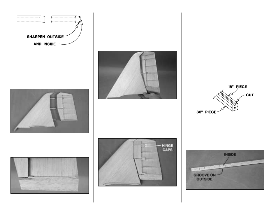
34. Without separating the rudder from the fin (until
instructed to do so), carefully remove the brass hinge
tube by pulling it out from the bottom. Use a #11 blade
and a cut-off wßheel or file to sharpen one end of the
brass hinge tube as shown in the sketch and reinsert it
with the sharpened end going upward into the rudder.
Attach the bottom of the tube to a drill or a rotary power
tool and drill a
clean
hole up through the rudder tip block
until the brass hinge tube exits the top.
❏
35. Now for the moment of truth. Pull the hinge tube
out and
carefully
separate the rudder from the fin.
There may be a few spots where you have inadvertently
glued the two together so be careful. Separate these
spots with a #11 knife if possible.
❏
36. Glue the leftover piece of 5/8" x 1-1/4" balsa to the
bottom of the rudder and sand it to the shape of the
rudder base block shown on the plan. Fill the space
between the base block and the bottom rudder ribs with
leftover 1/16" balsa.
❏
37. Use your sharpened brass hinge tube to drill a hole
through the rudder base block the same way you did the
rudder tip—only this time go down through the top.
❏
38. Round the LE of the rudder as shown on the plan
to allow for control movement. Test fit the rudder to the fin
with the brass hinge tube. Move the rudder side to side
and look for areas that interfere with smooth movement.
Trim where necessary to achieve the control throws in the
back of the manual. Make sure the rudder tip and the fin
tip do not interfere. If they do, sand the front of the rudder
tip until you have achieved enough clearance.
❏
39. Cut hinge caps from leftover 1/16" balsa and glue
them to the 3/32" ribs. These provide your covering with
something to bond to. Sand the hinge caps flush with
the rest of the rudder.
BUILD THE FUSELAGE
FRAME THE FUSELAGE TOP
❏
1. If you haven’t already done so, tape the left fuse
plan to the right fuse plan so the dashed alignment
marks match up. Cut the fuselage top view from the rest
of the plan and tape it to your building board. Cover the
plan with Plan Protector.
❏
2. Refer to the photo at step six and glue the die-cut
1/8" balsa former F1 to the front of the die-cut 1/8"
plywood cabin crutch, making sure F1 is at a 90 degree
angle. After the glue dries, bevel the sides of F1 to
match the sides of the cabin crutch.
❏
3. Pin the cabin crutch over its location on the plan.
❏ ❏
4. Gather the three 3/16" x 3/8" x 36" grooved
main stringers. Cut one of the stringers into two 18"
long pieces. Place an 18" main stringer on top of a 36"
main stringer so the ends align. Cut the stringers near
the ends at approximately a 45 degree angle as shown
in the sketch (use your miter box if you have one). The
two angled cuts will be spliced together at former F-9.
❏ ❏
5. Use a razor saw to cut small notches, 3/32"
deep, in the inside of the 36" stringer near the front so it
will bend around the cabin crutch.
- 20 -