Prepare the bottom of the wing for sheeting – Top Flite TOPA0500 User Manual
Page 42
❏ ❏
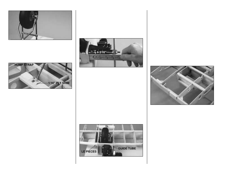
F16. Join your wheel to the assembly. Join the axle
assembly to the front strut and join the aft strut to the
strut connectors. Temporarily lock the axles to the front
strut with the set screws and center the wheel on the
axle and lock it into position with the 3/16" wheel collars
and set screws.
❏ ❏
F17. Make a 5/8" x 1" shim from leftover 1/16"
plywood and place it in the center of the aft landing gear
rail under the aft strut. Drill 1/16" holes for a nylon hump
strap and screw it to the rail with two #2 x 3/8" screws.
❏ ❏
F18. Temporarily mount the front strut to the
landing gear rails with two nylon flat landing gear
straps and four #2 x 3/8" screws.
❏ ❏
F19. Solder the strut connectors to the aft struts
only. A heavy duty soldering iron—around 80 watts—
works best for this.
❏ ❏
F20. In the future you can remove your wheels by
dismounting the aft strut from the landing gear rail and
loosening the axles from the front strut. Then, slide the
axles off the front strut and slip the axles out of the
strut connectors.
❏ ❏
F21. Remove the axles and file flat spots on the
struts for the set screws to lock onto.
❏
F22. Repeat steps F7 through F21 to build the other
landing gear strut and mount it to the wing the same way.
❏
F23. Remove any residual soldering flux from the
landing gear. You may paint the landing gear or coat it
with a fine film of houshold oil to protect it from rusting.
PREPARE THE BOTTOM OF THE WING
FOR SHEETING
❏ ❏
1. If you are installing 2-stroke engines, place one of
your engines on a Great Planes .20-.48 Adjustable
Engine Mount so the front of the drive washer is 4-3/16"
from the firewall. If you are installing 4-stroke engines,
position them on the mounts as close to the firewall as
possible. Use your Great Planes
Dead Center
Engine
Mount Hole Locator (GPMR8130) or another method to
mark the location of the engine mounting holes on your
engine mount. Drill the engine mount with a #43 drill. Tap
the holes with a 4-40 tap and mount the engine to the
mount with four 4-40 x 1" SHCS (socket head cap
screws) and #4 lock washers.
❏ ❏
2. Mount the engine mount to the left firewall with
four 4-40 x 1" SHCS, lock washers and flat washers.
❏ ❏
3. Drill a 1/8" hole for the throttle cable where it will
exit the firewall. Slip the 12" cable guide tube through
the firewall and the hole you previously drilled in the
center spar web, making sure the guide tube won’t
interfere with the retracts. Cut the guide tube to the
approximate length required.
❏ ❏
4. Mount the other engine and guide tube to the
right firewall the same way.
❏ ❏
5. If you haven’t already done so, glue the leading
edges on the center section to the inboard nacelle sides
and the W3 ribs. Glue the four die-cut 1/8" balsa
gussets to the center section where shown on the plan.
Use a piece of leftover shaped balsa LE to make the
small LE pieces that fit between the outer panel and
inner panel nacelle leading edges and glue them in
place (refer to the preceding photo).
❏ ❏
6. Cut out the portion of the outer W3 rib on both sides
of the center section to accommodate your throttle servos.
❏ ❏
7. Cut the aileron and flap (only if you’re building
working flaps) hinge blocks from two 1/4" x 1/2" x 24"
balsa sticks and glue them in place where shown on plan.
The aileron hinge blocks are centered on the TE spar
and the flap hinge blocks are on the bottom of the TE
spar. From leftover 1/8" balsa, make hinge blocks to fill
the space between the aft flap servo hatch rail and the TE
spar. Glue them in place where shown on the plan.
❏ ❏
8. Glue the rest of die-cut 1/8" balsa gussets (for outer
panels at rib W3A) in position where shown on the plan.
❏ ❏
9. Trim the ends of the bottom center section spars,
then sand the bottom of the wing so the ribs, spars, LE’s
and TE spars blend.
- 42 -