Top Flite TOPA0500 User Manual
Page 34
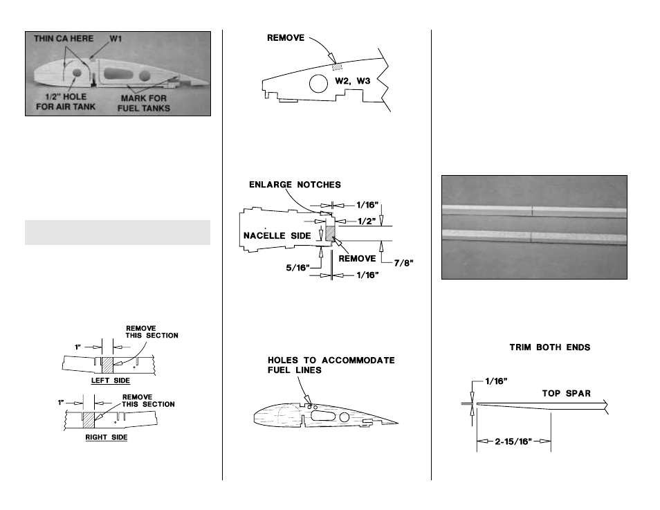
Refer to this photo for the following three steps.
❏
9. Mark one of the W1's for the fuel tanks as shown in
the photo. This is now the center W1. Cut partway through
the center W1 where marked for the fuel tanks. This partial
cut will make it easier to remove this section later.
Remember, “F-steps” are for
fixed landing gear only.
Remember, “R-steps” are for retracts only.
❏
R11. Cut an approximately 1/2" diameter hole through
the center W1 for the air line on the air tank. Apply
medium CA along the partially die-cut lines of the center
W1, an additional W1 and one of the W2's.
❏
R12. Remove a 1" section from both ends of the center
spar web where shown in the sketch to accommodate the
retract air cylinders.
❏
R13. Cut the two W2 ribs and the four W3 ribs along
the partially die-cut lines and remove the shaded area
shown in the sketch to accommodate the air cylinder
mounting rail.
❏
R14. Remove the shaded portion indicated in the
sketch from one inboard nacelle side and one
outboard nacelle side to accommodate the air cylinder.
Enlarge both spar notches by 1/16" in all four nacelle
sides as indicated in the sketch.
❏
15. Note the 1/4" holes in W1, W2 and W3 ribs for
your fuel lines. Make sure you punch out the balsa and
test fit your fuel lines in the holes. Enlarge the holes if
necessary so your fuel lines can easily pass.
❏
16. Gather both die-cut 1/8" balsa center TE spars.
Refer to the center TE spars on the plan. Cut both ends
of one of the center TE spars to accommodate the
dihedral joiner as shown on the plan. Glue the two
center TE spars together so the notches align.
❏
17. From two 1/4" x 3/8" x 36" basswood sticks, cut
two center section spars to the length shown on the
plan, cut two 5-3/8" long air cylinder mounting rails (if
you’re installing retracts) and cut two 2-7/8" long spar
joiner
wedges
(to be used later when joining the outer
panel to the center section).
❏
18. Mark the center of the spars all the way around to
help you align them with the center section assembly
later on.
❏
19. Trim both ends of one center section spar as shown
in the sketch. This is now the top center section spar.
❏
F10. Apply medium CA along the partially die-cut
lines of the three W1 ribs and the two W2 ribs.
- 34 -