Control locations 3, Electrical box 3, Rain/ manifold 3 – Reznor RDF Parts Manuals User Manual
Page 3
![background image](/manuals/709671/3/background.png)
Form P-RDF, P/N 270069 R6, Page 3
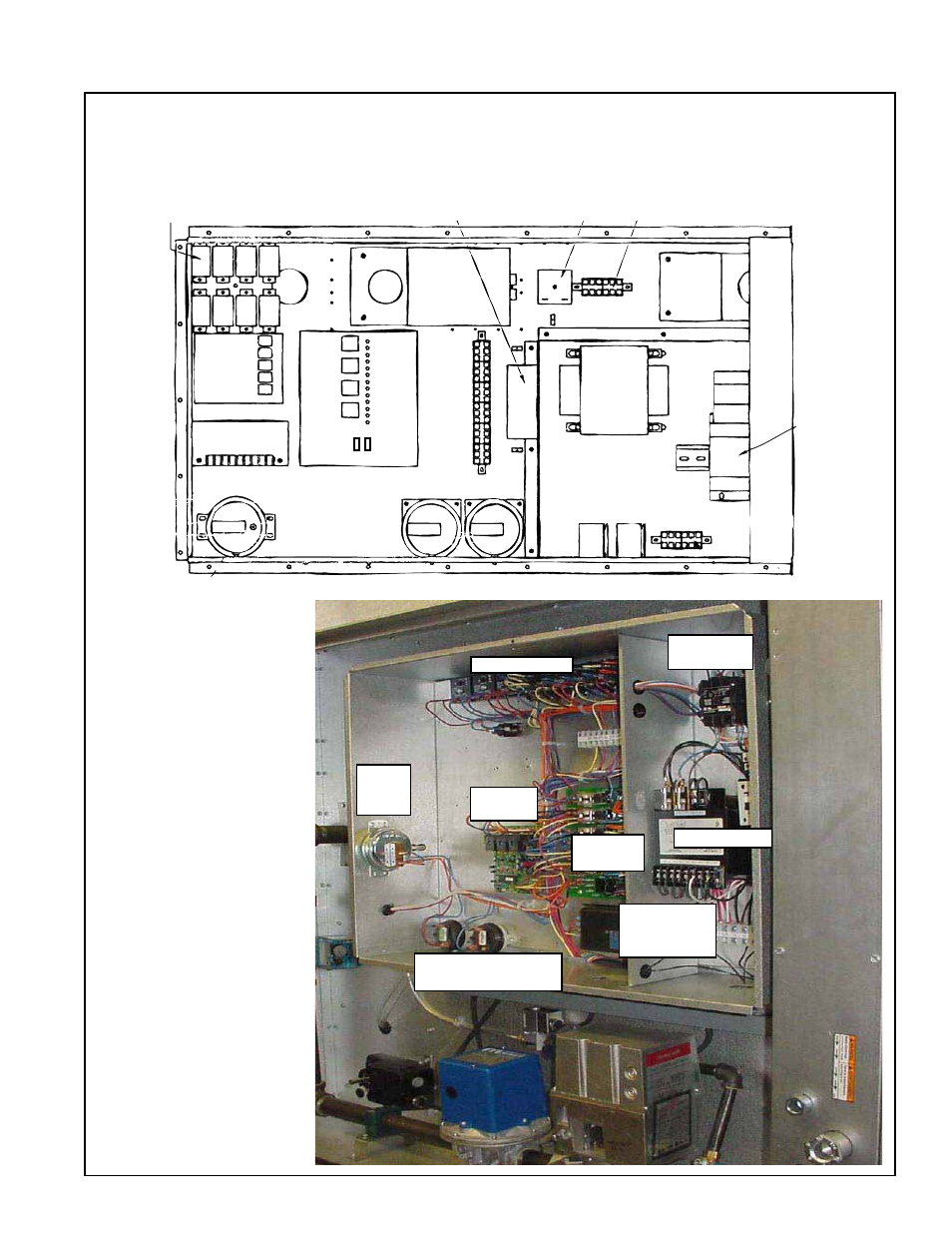
Electrical Control Compartment Typical Component Locations
See below and the following pages for P/N's and illustrations.
Control
Relays
Outside Air Cutoff
(high ambient limit control)
Time Delay
Relay
24-volt Terminals
Ignition
Module
Maxitrol Amplifier
or Signal Conditioner
Service
Switches
St
atus Light
s
Circuit
Board
24-V
olt T
erminals
Bypass
Damper
Motor
Return
Air
Damper
Motor
Motor
Starter
Transformer
Line Voltage
Terminals
Starter
Relay
Relay for
Optional
2-Speed
High
Low
Standard Pressure
Switches
Optional Dirty
Filter Pressure
Switch
NOTE: Illustration shows approximate locations of controls on RDF Series 3 systems. Manufacture of
Series 3 system began in 9/03. RDF systems manufactured prior to Series 3 have similar controls but
control locations are different. Because this product has experienced ongoing development, always provide
complete model and serial number when inquiring about or ordering replacement parts.
Model RDF Series 3
Control Compartment
Electrical
Box
Gas Train/
Manifold
Transformer
Contactor
or Starter
Amplifier
or Signal
Conditioner
Circuit
Analyzer
Ignitor
Module
High and Low
Pressure Switches
Control Relays
Dirty
Filter
Switch
- UDAP Unit Installation Manual (40 pages)
- UDBP Unit Installation Manual (44 pages)
- UEAS Unit Installation Manual (44 pages)
- VPS Unit Installation Manual (44 pages)
- VPT Unit Installation Manual (40 pages)
- VCS Unit Installation Manual (48 pages)
- CAUA Unit Installation Manual (44 pages)
- EEDU Unit Installation Manual (32 pages)
- LDAP Unit Installation Manual (44 pages)
- MASA Unit Installation Manual (40 pages)
- RDF Unit Installation Manual (28 pages)
- RPB Unit Installation Manual (40 pages)
- SC Duct Furnace Unit Installation Manual (40 pages)
- SSCBL Unit Installation Manual (60 pages)
- X Unit Installation Manual (32 pages)
- ZQYRA Unit Installation Manual (72 pages)
- ADF Unit Installation Manual (28 pages)
- F Unit Installation Manual (40 pages)
- PDH (Indoor PreevA) Unit Installation Manual (72 pages)
- MAPSIII Unit Installation Manual (76 pages)
- RDH (Outdoor PreevA) Unit Installation Manual (68 pages)
- RP (Outdoor Duct Furnaces) Unit Installation Manual (32 pages)
- YDHA Unit Installation Manual (76 pages)
- OH Unit Installation Manual (28 pages)
- RBL (Cabinet Blower) Unit Installation Manual (12 pages)
- REC (Evaporative Cooling) Unit Installation Manual (12 pages)
- RIHN Unit Installation Manual (20 pages)
- UDAP Option - Installation - Power Venting (12 pages)
- UDAS Option - Installation - Separated Combustion Venting (16 pages)
- WS Unit Installation Manual (15 pages)
- EBHB Option - Installation - Thermostat Kit (2 pages)
- EFMA Unit Installation Manual (27 pages)
- EWHB Unit Installation Manual (9 pages)
- EXUB Unit Installation Manual (16 pages)
- XAWS Unit Installation Manual (12 pages)
- XAWU Unit Installation Manual (12 pages)
- XBWU Unit Installation Manual (12 pages)
- MAPS III Option - Installation - Energy Recovery Module Installation (12 pages)
- UDAP in sizes 30 through 125 Option - Installation - Ceiling Suspension Kit (2 pages)
- UEAS Option - Installation - Downturn Nozzles - V3 (4 pages)
- UDBP Option - Installation - Polytube Adapter Instructions (4 pages)
- UDBS Option - Installation - Vertical Louvers - V3 Series (2 pages)
- B Option - Installation - Blower/Filter Cabinet (4 pages)
- PDH with 1-stage gas control or 2-stage gas control Gas Conversion Kit Instructions (8 pages)
- VP series infrared heaters High altitude conversion instructions (12 pages)