LAARS NeoTherm LC NTV1700 - Install and Operating Manual User Manual
Page 72
LAARS Heating Systems
Page 68
About the “Time of Day” Function
If the “time of day” function is enabled, the control
system can be set to maintain different temperatures
for central heat and domestic hot water (other than
the normal setpoints) in the system at certain times
of the day. Normally this function is used to switch
to lower temperatures at night, when the central
heating or domestic hot water demand is reduced.
When the controller acting as the Lead/Lag Master
receives a time of day input, the controller shifts
to the special setpoints entered for central heat and
domestic hot water.
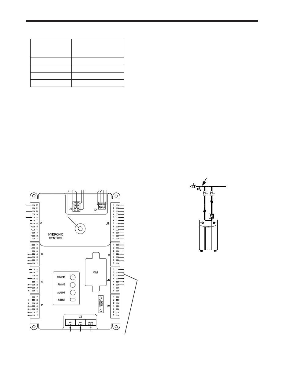
The input for the Time of Day function must be
wired to pins 2 and 3 on connector J10.
Fig. 90 – Connections for “Time of Day” Function
Job J - Install the System Sensor and
Adjust the Setpoint
(This is a Lead/Lag function – do this once for the whole Lead/
Lag system. Make the connections to the controller set up as the
Lead/Lag Master – usually the Primary controller on Boiler 1.)
1. Install the System sensor at the location shown
in Fig. 91. Connect the System sensor to the
System terminals on the controller acting as
the Lead/Lag Master (usually the Primary
controller on Boiler 1.) Use terminals 3 and 4
on TB6.
2. Adjust the Lead/Lag Central Heat Setpoint
to the desired temperature to be used by the
system.
How to get there – Adjust CH Setpoint
Home Page
Screen
Screen
Configuration Screen
Line 2 = CH Setpoint
Fig. 91 – Mounting Location for System Sensor
Job K - Set the Lead Lag Outdoor Reset and
Warm Weather Shutdown
(This is a Lead/Lag function – do this once for the whole Lead/
Lag system. Use the controller set up as the Lead/Lag Master –
usually the Primary controller on Boiler 1.)
For more information on the outdoor reset function,
see the explanation which follows.
1. Install the outdoor air temperature sensor and
make the connections to the outdoor air sensor
terminals on the controller acting as the Lead/
Lag Master (usually the Primary controller on
Boiler 1.) Use terminals 1 and 2 on TB7.
Table 16 – Base Load Settings
Number
of boilers
Installed
Base load min.
1
65%
2
50%
3
30%
4
30%
Pins 2 and 3 on
connector J10