LAARS NeoTherm LC NTV1700 - Install and Operating Manual User Manual
Page 18
LAARS Heating Systems
Page 14
5. Locate the vent terminal so that it cannot
be blocked by snow. The installer may
determine that a vent terminal must be
higher than the minimum shown in codes,
depending upon local conditions.
6. Locate the terminal so the vent exhaust does
not settle on building surfaces or other nearby
objects. Vent products may damage surfaces or
objects.
7. If the boiler or water heater uses ducted
combustion air from an intake terminal located
on the same wall, see Figures 10 and 11 for
proper spacing and orientation.
If the vent termination is located in an area exposed
to high winds, an optional PVC tee (the same
diameter as the vent pipe) may be used. The tee’d
vent termination offers greater protection from wind
related operating issues.
3.3.2 Side Wall Combustion Air Terminal
The LAARS side wall combustion air terminal
must be used when the heater takes air from a side
wall. (See Table 3.) Contact Laars for AL29-4C
termination fittings. Consider the following when
installing the terminal. (See Figures 10 and 11).
1. Do not locate the air inlet terminal near a
source of corrosive chemical fumes (e.g.,
cleaning fluid, chlorine compounds, etc.).
2. Locate the terminal so that it will not be subject
to damage by accident or vandalism. It must be
at least 7 feet ( 2.1 m) above a public walkway.
3. Locate the combustion air terminal so that it
cannot be blocked by snow. The National Fuel
Gas Code requires that it be at least 12 inches
(30 cm) above grade, but the installer may
determine it should be higher, depending upon
local conditions.
4. If the NeoTherm LC is side-wall vented to the
same wall, locate the vent terminal at least 1
foot (0.3 m) above the combustion air terminal.
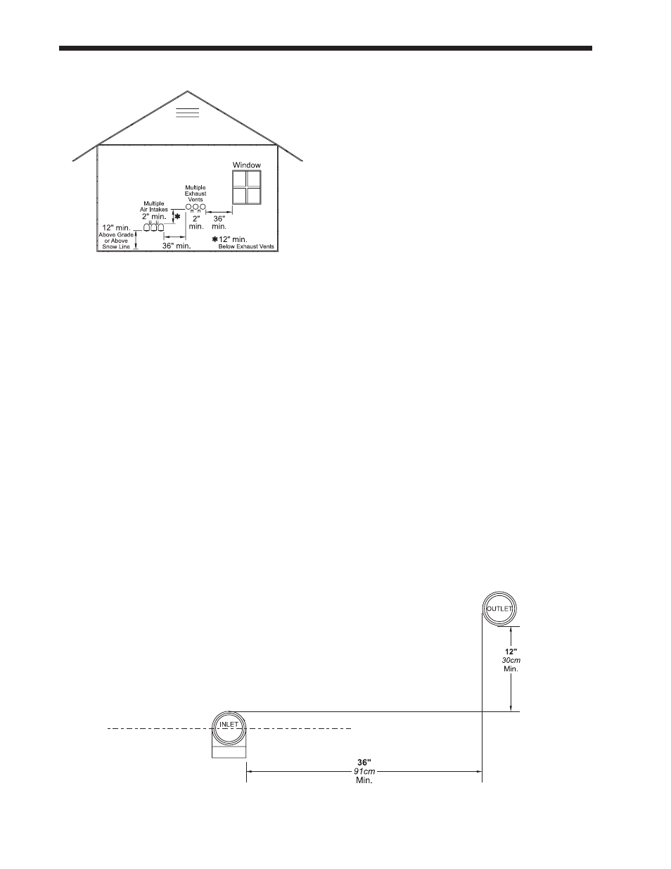
5. Multiple vent kits should be installed such that
the horizontal distance between outlet group
and inlet group is 36” (90 cm). (See Figure
10.)
6. The vent outlet must be at least 12” above the
top of the air inlet, and must be at least 36” (90
cm) horizontally from the air inlet. (See Figure
10.)
Fig. 11 - Minimum Venting Distance
IMPORTANT: All terminals must be placed so that they remain at least
12” above the expected snow line. Local codes may have more specific
requirements, and must be consulted. Refer to the NFPA54 National Fuel
Gas Code and your local codes for all required clearances for venting.
Fig. 10 - Multiple Side-Wall Terminals, Air and
Vent