LAARS NeoTherm LC NTV1700 - Install and Operating Manual User Manual
Page 5
NeoTherm LC Boilers and Water Heaters
Page 1
Section 1
GENERAL INFORMATION
1.1 Introduction
This manual includes information which will help
you to install, operate, and maintain the NeoTherm
LC 1000 and 1700 systems. Please read this manual
completely before proceeding with the installation.
If you have any questions regarding this equipment,
please consult the LAARS Heating Systems factory,
or a local factory representative. Many operating
problems are caused by improper installation.
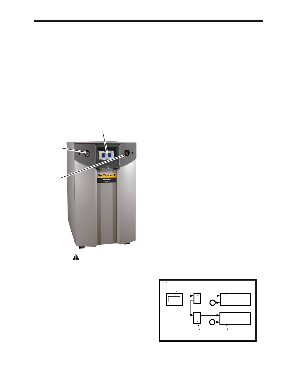
Pressure and
temperature
gauge
Touch Screen Display
(behind the plastic cover
which slides downward)
Power switch
WARNING
NeoTherm LC units
must be installed in
accordance with the procedures detailed in
this manual, or the LAARS Heating Systems
warranty will be voided. The installation must
conform to the requirements of the local
jurisdiction having authority, and, in the United
States, to the latest edition of the National Fuel
Gas Code, ANSI Z223.1/NFPA54. In Canada,
the installation must conform to the latest edition
of CSA B149.1 Natural Gas and Propane Gas
Installation Code, and/or local codes. Where
required by the authority having jurisdiction,
the installation of NeoTherm LC boilers must
conform to the Standard for Controls and Safety
Devices for Automatically Fired Boilers, ANSI/
ASME CSD-1. Any modifications to the boiler,
its gas controls, or wiring may void the warranty.
If field conditions require modifications, consult
the factory representative before initiating such
modifications.
1.2
About the NeoTherm LC
Touch Screen Display
The NeoTherm LC has an advanced control system
which can perform many functions. This is part
of the reason why the NeoTherm LC 1000 or 1700
can deliver such outstanding performance. You
can access the control system using the ‘Touch
Screen Display’ (see Section 8). There are several
“branches” in the control software, and many
different display screens. For clarity, throughout
this manual we have made a special effort to show
you how to reach each of the important setup and
operating functions. We have done this in two ways:
•
In many cases, we have shown you the actual
touch screen display that you will see while
performing a function.
•
Sometimes, instead of showing the screens, we
have just listed the series of choices you should
make in order to reach the section you want.
The arrangement of the control software is actually
quite logical, and after you have worked with it a bit,
you will not have any problems “finding your way
around.” We just want to give you some help with
the first part of the process, when you are “getting
used to” the control system .
Later in this manual, we will detail information on
the setup and operating procedures. There are a
couple of concepts you will need to understand right
from the start.
•
Each boiler has two controllers (internal
electronic burner controllers) and two burners,
as shown in Fig. 1.
•
A single Touch Screen is used to communicate
with these two controllers.
Primary
burner
Primary
controller
Gas
valve
Gas
valve
Secondary
controller
Secondary
burner
Touch
Screen
Boiler 1
Fig. 1 – Control Arrangement in a Single-Boiler
Installation