LAARS NeoTherm LC NTV1700 - Install and Operating Manual User Manual
Page 36
LAARS Heating Systems
Page 32
The System pump connections are located on
terminal block 5 (5-6 on TB5) in the control panel.
(See Figure 20.) The System pump contacts are rated
for 120 VAC, 7.4 Amps. To use the contacts, power
must be supplied on one terminal with the other
terminal wired to the relay controlling the pump.
The DHW pump connections are located on terminal
block 5 (7-8 on TB5) in the control panel and are
rated for 120 VAC, 7.4 Amps. To use the contacts,
power must be supplied on one terminal, and the
other terminal wired to the relay controlling the
pump.
Additional 120 VAC circuits may be required for the
pumps.
7.3
24 VAC Transformer with Integral
Circuit Breaker
24 VAC is supplied by a transformer mounted on the
control panel. All 24 VAC power is supplied through
a circuit breaker that is part of the transformer. The
transformer is then connected to terminal blocks 1
and 2 (TB1 and TB2).
7.4
Signal Connections
See Section 9 for details on the following
connections:
• System sensor
• Call for heat/thermostat
• Outdoor air temperature sensor
• Aquastat for domestic hot water
• External control connections
7.5
Optional Field Connections
Optional components, such as low water cutoffs,
flow switches, additional high limits and other field
supplied devices can be installed as shown on the
wiring diagram (Fig. 22).
7.6 Ladder and Wiring Diagrams
See Figures 21 and 22.
Caution
When servicing controls, label all wires prior to
disconnection. Wiring errors can cause improper
and dangerous operation. Verify proper operation
after servicing
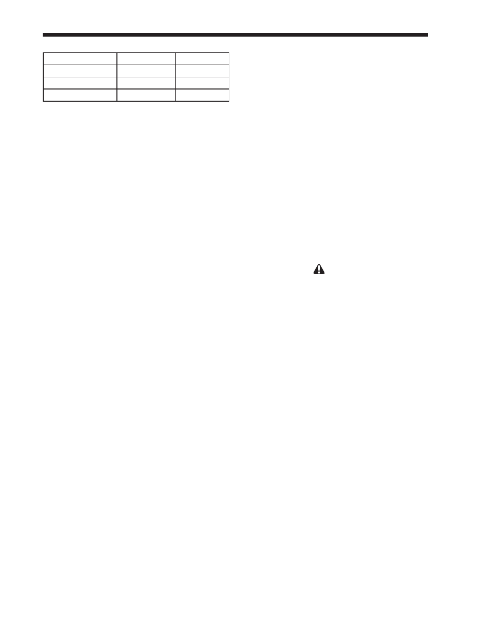
Table 10 - Electrical Data
Model
1,000
1,700
Voltage
120 V AC
120 V AC
Current - FLA
12 A
30 A
Current - Nominal
5 A
16 A