E.1.4 using the sensor on the crank, E.1.5 typical set-ups – s3 – Haltech F10X User Manual
Page 106
F10X Manual
106
E.1.4 Using the Sensor on the crank
After a suitable mounting location for the sensor has been found the engine should be
positioned at approximately 75
° BTDC on cylinder no.1 compression. The magnet should
now be placed in the aluminium disk, making sure the magnet is in line with the sensor when
the engine is in this position. This is now the reference point for all the other magnets. The
number of cylinders will determine the number of magnets required and the angle of
installation. If the sensor is to be used on the Camshaft, the number of magnets will need to be
doubled. The adjustment of the air gap will be determined by the strength of the magnets
used. This should be tested once the wheel assembly has been installed. Typical air gap is (2 –
8mm) Checking the Engine Data page for steady RPM is usually a good indication that the air
gap is acceptable.
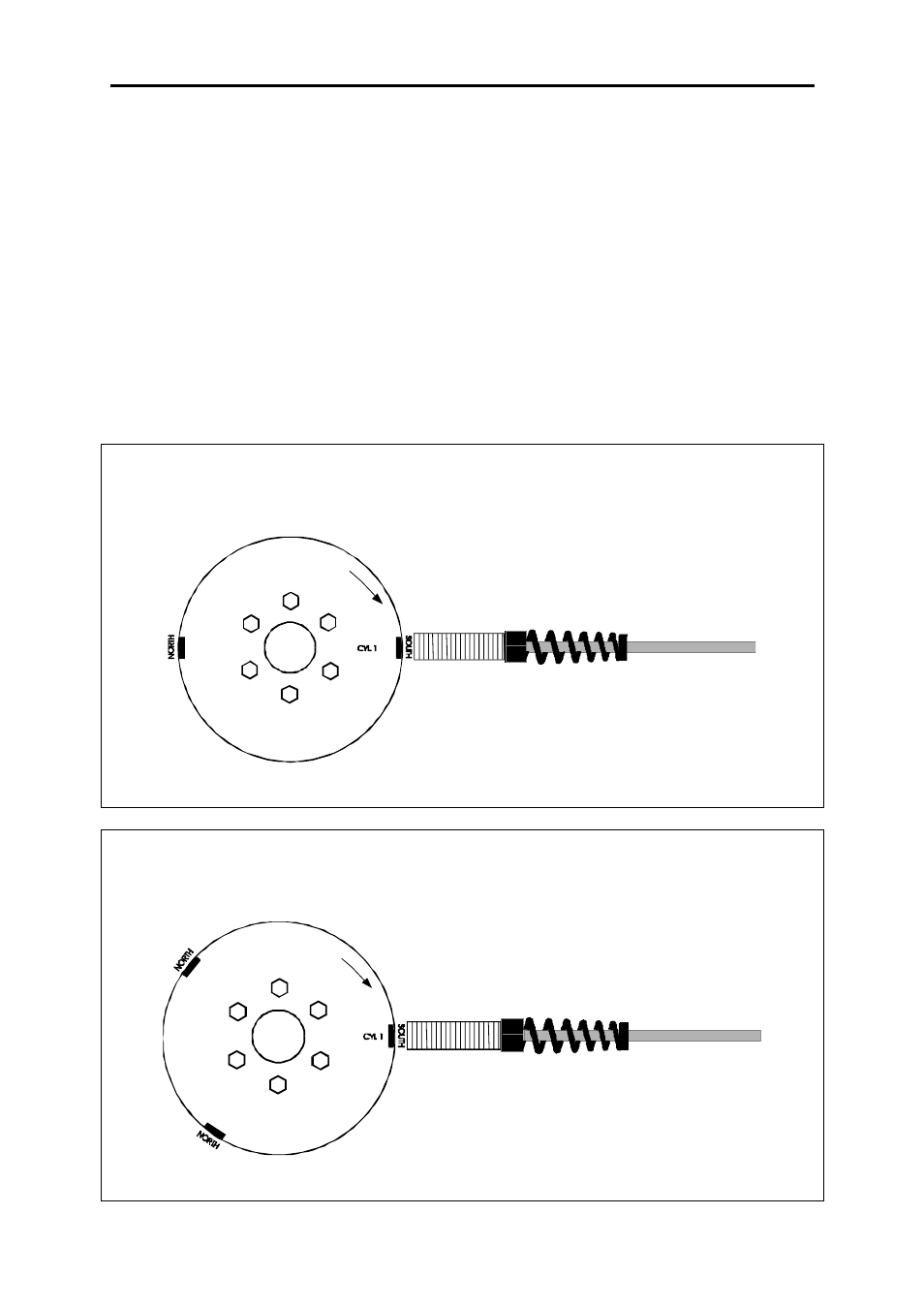
E.1.5 Typical set-ups – S3
4 cylinder / 2 rotor Engine
For a four cylinder 2 magnets are required in total, positioned exactly 180
° apart.
Figure 1: Typical 4 cylinder/ 2 rotor application
6 Cylinder / 3 Rotor Engine
For a six cylinder 3 magnets are required in total, positioned exactly 120
° apart.
Figure 2: Typical 6 cylinder/ 3 rotor application