E.1.3 haltech hall effect sensors – Haltech F10X User Manual
Page 105
F10X Manual
105
E.1.3 Haltech Hall Effect Sensors
The Haltech Hall Effect sensor is a two-channel device that can be used to trigger the Haltech
range of ECU’s in a wide range of applications. As the Haltech Hall Effect sensor is dual
channel, it can provide this synchronisation pulse as well as the trigger signal. The
synchronisation pulse is not required when using the F10X. Due to this fact, no further
reference will be made to the synchronisation pulse.
The principle behind its operation is quite simple. As a magnet passes the sensor, the output
state of the sensor, changes from high to low. The position of the magnets determines the
output signals from the sensor.
The S3 Hall Effect Sensor
The S3 sensor which is identified by a black cable gland, operates in the following way:
As a North pole or South pole passes the sensor face the signal in the primary channel (PIN
B) is switched from a high to a low state.
Note: Due to the way the F10X is triggered, the Rare Earth Magnets can be
placed in the trigger wheel with either North or South pole facing the sensor.
Note: magnets should always be mounted in a non-ferrous material such as
aluminium, stainless steel or titanium.
Many installers have successfully mounted the rare earth magnets in non-ferrous surrounds
such as modified aluminium and stainless steel bolts, and installed the bolts into ferrous
material.
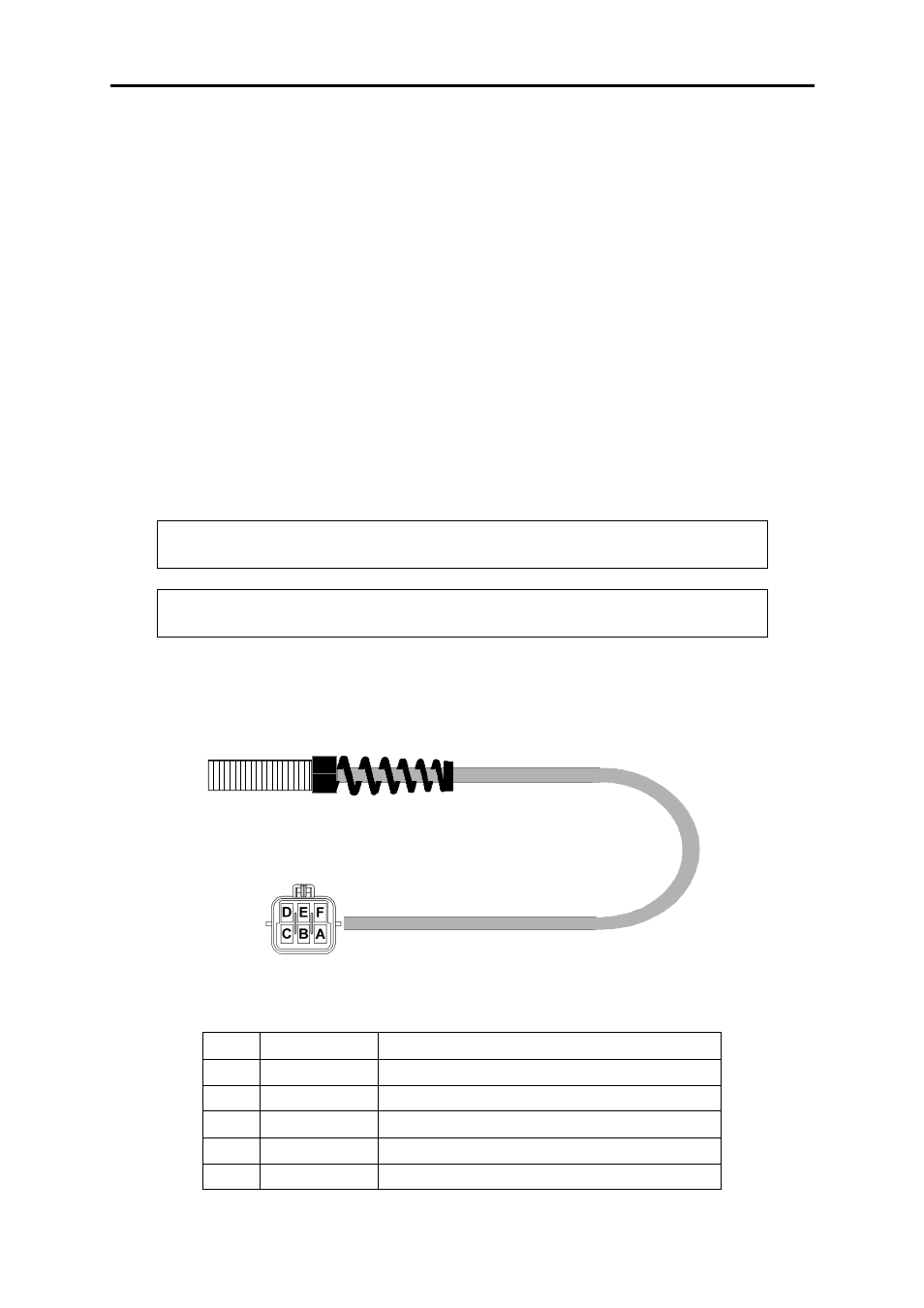
SENSOR PIN OUTS
A BLUE GROUND
B YELLOW
TRIGGER
C N/C
D N/C
E
GREEN
NOT USED ON F10X
F
RED
+ 12 VOLTS