Appendix e trigger interface, E.1 the trigger type, E.1.1 hall effect and optical triggers – Haltech F10X User Manual
Page 103
F10X Manual
103
APPENDIX E
TRIGGER INTERFACE
The ECU is capable of accepting two different trigger types. This appendix will explain the
trigger systems the ECU supports.
The following fields configure the trigger input:
Trigger Type
Trigger
Edge
Trigger
Pull-up
The trigger interface will be described below in terms of the above fields to simplify
configuration of the ECU trigger interface.
E.1 The Trigger Type
The 3 types of trigger signals used to trigger the ECU are: Coil Negative/Tacho Output,
Optical and Hall Effect. Optical and Hall Effect trigger sensors are electrically identical when
used with the ECU and from here on any reference to Hall Effect triggers refers to optical
triggers also. The Coil Negative and Tacho Output triggers produce a different signal to that
of Hall Effect sensors and therefore require a different input and different ECU settings.
E.1.1 Hall Effect and Optical Triggers
Hall effect and optical triggers produce a square wave signal when connected to the ECU and
can be treated the same electrically. The ECU specification allows the use of a Hall effect
device that outputs a low of 0V and high of between 5V and 12V, the switching threshold is
set to 2.5V. Hall effect sensors normally have 3 connections: power, signal and ground, this
is by no means the only classification that should be used for sensor identification, if in doubt
contact your Haltech dealer. Please note that the Haltech S3 & S4 Hall Effect sensors have 4
connections, one of which is a synchronisation signal, which is not required by the F10X.
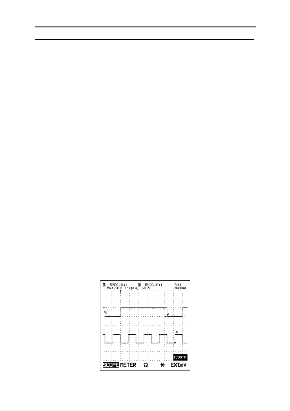
Below is a trace of the signal of a “Standard Trigger” for a 4-cylinder distributor.