Final hookups and checks – Great Planes P-51D Mustang 40 Kit - GPMA0175 User Manual
Page 44
squeeze out. 4. Allow to dry without disturbing for at
least 24 hours. 5. Remove the tape, then remove the
wing from the saddle (leaving the waxed paper or plastic
wrap in place). 6. Gently pull the waxed paper or plastic
wrap away from the sealer. 7. Using a new single-edge
razor blade, trim the sealer flush with the wing fillets, and
along the inside of the fuselage.
RE-INSTALL ENGINE & RADIO
Re-install the engine, propeller, battery, receiver, servos,
control horns, pushrods, main LG, and wheels. Attach the
wing to the fuselage.
*If possible, first attempt to balance the model by chang-
ing the position of the servos and receiver battery. If you are
unable to obtain good balance by doing so, then it will be
necessary to add weight to the nose or tail to achieve the
proper balance point.
NOTE: Now that you have the servos located in a
position that allows the model to balance at the
recommended C.G., you may now securely glue the
servo rails and servo rail locking plates to the fuselage
sides. Refer back to the section on radio installation, and
finish hooking up the pushrods as per the instructions.
FINAL HOOKUPS AND CHECKS
BALANCE YOUR MODEL
NOTE: This section is VERY important and must
not be omitted! A model that is not properly balanced
will be unstable and possibly unflyable.
D 1. Accurately mark the balance point on the top of the
wing on both sides of the fairing. The balance point is shown
on the plan (CG), and is located approximately 5-3/8 inches
back from the leading edge at the center (5/8-inch back from
the center of the spar). This is the balance point at which your
model should balance for your first flights. Later, you may
wish to experiment by shifting the balance up to 5/16"
forward or back to change the flying characteristics. Mov-
ing the balance forward may improve the smoothness and
arrow-like tracking, but it may then require more speed for
takeoffand make it more difficult to slow down for landing.
Moving the balance aft makes the model more agile with a
lighter and snappier "feel" and often improves knife-edge
capabilities. In any case, do not balance your model outside
the recommended range.
D 2. With the wing attached to the fuselage, all parts of
the model installed (ready to fly), and an empty fuel tank,
hold the model upside down with the stabilizer level.
D 3. Lift the model at the CG marks. If the tail drops
when you lift, the model is "tail heavy" and you must add
weight* to the nose to balance. If the nose drops, it is "nose
heavy" and you must add weight* to the tail to balance.
NOTE: Nose weight may be easily installed by using a
Prather "Spinner Weight" (available in assorted weights, up
to 2 ounces), or by gluing strips of lead into the engine
compartment under the engine. Tail weight may be added by
using Prather "stick-on" lead weights, and, later, if the
balance proves to be OK you can open the fuse bottom and
glue these in permanently.
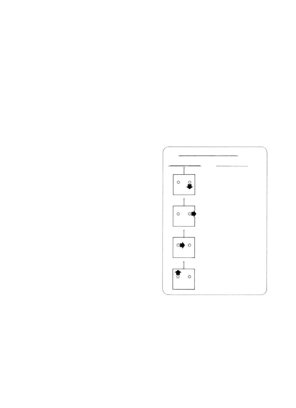
D 1. Make sure the control surfaces move in the proper
direction as illustrated in the following sketches:
F O U R - C H A N N E L SETUP
D 2. Adjust your pushrod hookups as necessary to pro-
vide the proper control surface movements as listed on Page
39.
CONTROL SURFACE
MOVEMENTS
ELEVATOR MOVES UP
RIGHT AILERON MOVES UP
LEFT AlLERON MOVES DOWN
RUDDER MOVES RIGHT
CARBURETOR WIDE OPEN
T R A N S M I T T E R
S T I C K M O V E M E N T S
44