Great Planes P-51D Mustang 40 Kit - GPMA0175 User Manual
Page 29
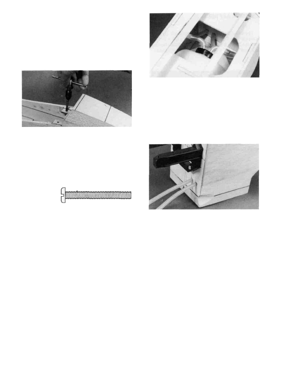
down plate in the fuselage. Try to drill straight in, perpen-
dicular to the 1/16" ply bolt plate. IMPORTANT!: Do not
allow the wing to move while drilling!
D 13. Remove the wing and re-drill the holes in the wing
only to 1/4".
D 2. Try sliding the tank in through F-2. If the opening is
not large enough, sand or file the opening until the tank slides
in easily.
D 3. Temporarily install the engine mount and note how
far the mounting screws protrude into the fuel tank compart-
ment. Remove the screws and cut them off so they do not
protrude more than 1/8" (to prevent puncturing the fuel tank).
D 14. Use a 1/4-20 tap and a tap wrench to cut threads in
the ply hold-down plate in the fuselage.
D 15. Harden the threads in the hold-down block with thin
CA glue, then re-tap the threads after the glue is completely
dry.
D 16. Trial Fit the wing to the fuse using the two 1/4-20
nylon bolts provided. You may cut the bolts off to their proper
length, so they protrude about 1/4" below the hold-down plate
in the fuselage,
1/4 - 20 Nylon Wing Bolt
D 17. Later you will apply foam wing seating tape or
silicone sealer to the wing saddle. To allow space for this
wing cushion material, you may sand the saddle slightly in
the areas where the wing touches the saddle, to provide a
small gap.
FIT FUEL TANK and FUELPROOF TANK
COMPARTMENT
D 1. Assemble your 10 oz. fuel tank. We recommend
bending the brass tubes as shown in the photo to prevent them
from cutting through the silicone fuel lines if pressed against
the firewall. (Try not to "kink" the tubes when bending,
however).
D 4. Drill two holes (7/32" or size to fit your fuel tubing)
for your fuel tubing vent and fill lines. The location of these
holes will depend somewhat upon the type of engine you are
using, and whether or not you will be using an external fueling
valve, such as the "Dubro #334 Kwik-Fill Fueling Valve."
D 5. Now remove the engine mount and fuelproof the
inside of the fuel tank compartment and the front of F-l by
brushing on a coat of polyester resin or 30-minute epoxy
thinned with alcohol.
D 6. You may permanently install the fuel tank at this
time, or you may wait until the plane is nearly completed. If
you do it now it will be easier to feed the fuel lines through
F-1, and to make sure there are no kinks in the lines; however,
you'll have to work around them while completing the nose.
When you install the tank, be sure to cushion it from vibration
and prevent it from moving by surrounding the tank on all
sides (and front) with latex foam rubber. Leave several
inches of extra fuel tubing in front of F-1 (you can cut off the
excess later). The photo at step 2 shows how to route the fuel
tubing to prevent kinking.
29