Great Planes P-51D Mustang 40 Kit - GPMA0175 User Manual
Page 38
D 2. Remove a sufficient portion of the W-l ribs to fit
your servo, leaving "shelves" on which to glue the 1/8" ply
rails. (See the plan to determine the depth). NOTE: A
Dremel Moto Tool with a 1/8" router bit is excellent for this,
but it may also be done with an Xacto knife and a long-nose
pliers.
D 3. Make two aileron servo rails from the 1/8" ply die-
cutting scrap, and glue them in place. (See the side view of
the aileron servo installation on the plan).
D 4. Mount the aileron servo using the screws provided
with your radio.
D 5. Screw the nylon aileron clevises approximately 2/3
of the way onto the threaded end of the two 12" steel wire
pushrods.
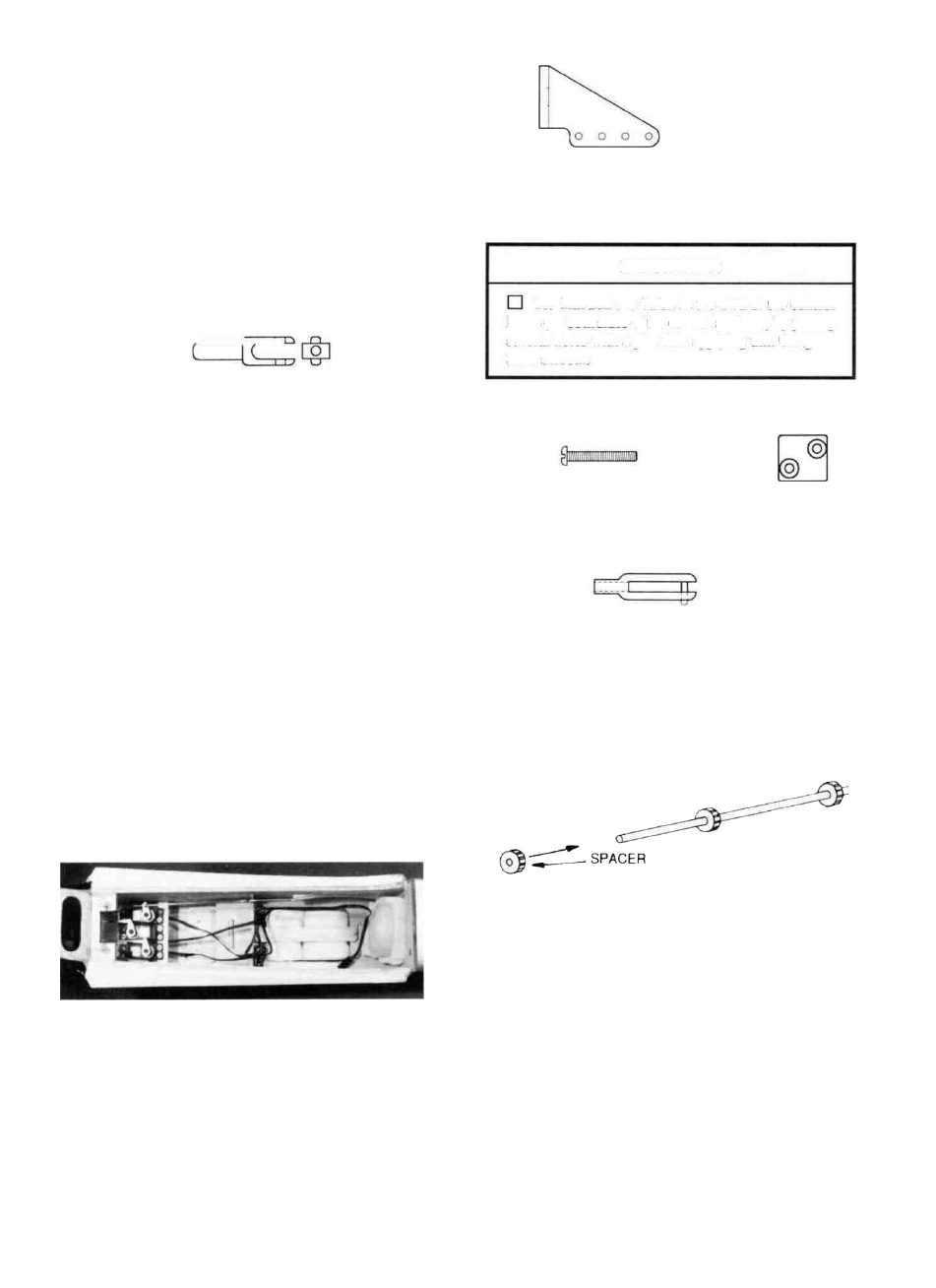
Nylon
Control Horn
D 10. Hold the nylon control horns on the elevator and
rudder in the positions shown on the plan and mark the
mounting hole locations. Drill 3/32" holes at these locations.
IMPORTANT!
D 11. Harden the balsa in the area of the control
horns (on both sides of the control surfaces) by poking
several holes with a pin, then applying thin CA glue.
Sand smooth.
NYLON AILERON CLEVIS AND CONNECTOR
D 6. Screw the nylon aileron clevis connectors onto the
aileron torque rods.
D 7. Attach the clevises to the clevis connectors, then,
with the ailerons in the neutral position, mark the pushrod
wires where they cross the holes in the servo arm. Remove the
pushrods and make a "Z-bend" in the rods at that point, using
a "Z-bend pliers" or a standard pliers.
D 8. Remove the servo wheel from the servo and work
the Z-bends into the wheel (NOTE: You may have to enlarge
the servo wheel holes with a 5/64" diameter drill bit). Replace
the servo wheel and check the operation of the ailerons. (See
page 39 for the recommended amount of aileron movement).
REMEMBER: Plan your servo installation carefully,
as your setup may differ from the plans and photos,
depending on which engine you use.
D 12. Mount the horns with 2-56 screws and the nylon
nutplates which were attached to the horns.
2-56 x 5/8
Machine Screw
Nutplate
D 13. Screw a nylon clevis onto the threaded end of each
long steel wire pushrod. NOTE; Screw them on all the way
until the threads are protruding inside the clevis.
Nylon Clevis
D 14. Cut the short length of 1/8" diameter plastic tube into
several pieces, approximately 1/4" long. Slide at least six of
these pieces onto each of the long pushrod wires and space
them approximately 2-1/2" apart (do not glue yet). NOTE:
If these tubes do not slide on easily, cut them to a shorter
length.
NOTE: While installing the pushrods, position the above
plastic tube spacers so they always stay inside the pushrod
guide tubes. If the tubes are not a tight friction fit on the
pushrod wires, apply a drop of thin CA to secure them.
D 9. Re-mount the elevator, rudder and throttle servos in
the fuselage. BUT DO NOT GLUE THE RAILS IN
PLACE! Remember, you want to maintain the ability to
move the servos if necessary for balancing. (See balancing
section later in this book).
D 15. Insert the pushrod wires into the pushrod guide
tubes (previously installed) and attach the clevises to the
elevator and rudder horns.
38