Great Planes P-51D Mustang 40 Kit - GPMA0175 User Manual
Page 18
NOTE: Step 4 is for side mounted or upright mounted
engines only.
D 4. Cut the right wing tip loose from the wing and use
a Dremel Moto Tool to hollow out the wing tip. (This will
help to compensate for the weight of the engine head and
muffler).
D 5. Now securely glue the right wing tip in place.
D 6. Cut a 1-1/4" piece from each aileron for the fixed
outboard TE, and cut one end of these pieces to an angle to
match the plan. Glue these pieces to the wing, positioning
them carefully so they line up with the top and bottom of the
wing.
D 7. Sand the wing tip to blend with the TE piece you just
installed.
INSTALL AILERONS
NOTE: Do not glue the aileron hinges until after your
model has been covered.
U 1. Draw an accurate centerline along the LE of the
tapered balsa ailerons and the wing TE.
D 2. Check the length of your ailerons against the actual
aileron openings and trim the ailerons as necessary. You
should provide approximately 1/16" gap at each end of the
ailerons.
D 5. Use the sharpened 1/8" diameter brass tube to cut a
groove in the leading edge of the ailerons to accept the
torque rods. Trial fit the ailerons onto the torque rods and cut
or file as necessary until they fit.
D 6. Lay the ailerons on the plan and mark the hinge
locations on the ailerons. Place the ailerons against the wing
TE and transfer the marks over to the wing.
D 7. Cut the hinge slots in the ailerons and wing TE using
an Xacto knife.
D 8. Sand the leading edge of the ailerons to the same
"V-shape as shown on the wing rib detail drawing.
D 9. Insert the hinges into the slots and trial fit the
ailerons in place on the wing. Do not glue the hinges until
after you have covered the wing.
There should be no hinge gap!
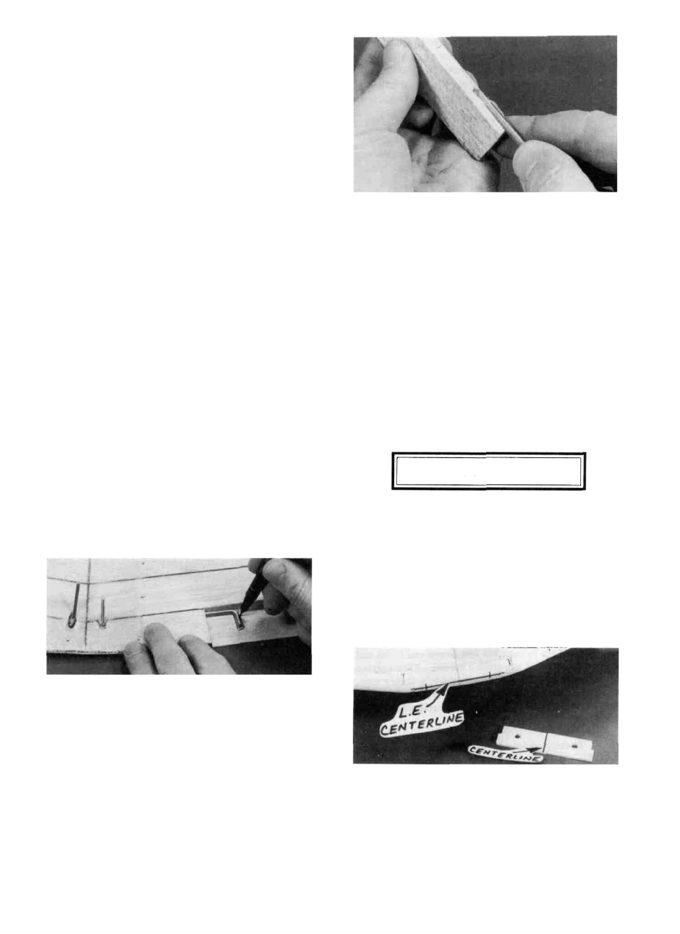
D 3. Lay the ailerons in place in the openings, with the
torque rods resting on top of the ailerons. Mark the torque
rod locations on the top of the ailerons.
D 4. Drill a 7/64" hole in the ailerons at the torque rod
locations, starting at the leading edge centerline and drilling
straight in to the proper depth. (The hole is drilled slightly
oversize to allow for positioning, and to create a hard epoxy
"sleeve" around the wire).
TEMPORARILY INSTALL WING DOWELS
D 1. Mark a horizontal centerline on the wing LE. Also
mark a vertical centerline on the die-cut 1/8" ply former
F-2A.
18