Great Planes P-51D Mustang 40 Kit - GPMA0175 User Manual
Page 26
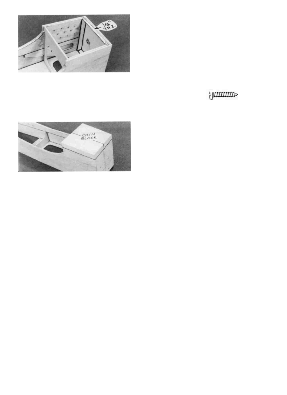
D 19. Cut pieces of 1/4" balsa triangle to fit around the aft
edges of F-l, and glue them in place.
D 20. Find the two 9/16" x 2-1/16" x 4-1/4" balsa blocks
and edge glue them together to make the chin block.
Drill Engine Mount
D 1. Place the engine pointing straight ahead on the
mount and mark the mounting hole locations on the mount.
At the marked locations, accurately drill 7/64" (or #36) holes.
NOTE: If you have access to a drill press, use it for drilling
these holes to insure that they are drilled vertically.
D 2. Now you may use one of the following methods to
attach your engine to the mount:
Method 1: Screw the #6 x 3/4" sheet metal screws
(provided in the kit) through the engine mounting flange and
into the mount. When first installing these screws, put a drop
of oil into each screw hole.
D 21. Sand the bottom edges of the fuse sides, F-l and
F-2 to make a flat, even surface for the chin block. Glue the
chin block in place as shown on the plan. NOTE: The aft
edge of the chin block must extend at least 1/8" behind the aft
edge of F-2. Now sand the edges of the chin block even with
the fuse sides and the front of F-l. Sand the aft edge of the
chin block to a slight angle as shown on the plan. You may
temporarily lay F-2A in position as a guide when sanding the
aft edge of the chin block.
Method 2; Cut threads into the holes you just drilled
using a 6-32 tap and tap wrench. If you use this method you'll
have to supply your own bolts (6-32 x 1" socket head cap
screws) for attaching the engine to the mount. NOTE: 8-32
hardware is recommended if you are installing a 4-cycle
engine.
INSTALL PUSHROD GUIDE TUBES
NOTE: Although you may choose to wait until later,
this is the best time to install the pushrod guides, because
the fuselage is wide open and it is very easy to work
inside.
IMPORTANT: Before proceeding, plan your servo
and pushrod installation. Especially note on which
side of the fuselage the throttle pushrod will be located.
Remember that the throttle arms of 2-cycle and some
4-cycle engines arc on opposite sides. It will be helpful
to actually sketch your pushrod locations on the plans
with a pencil. It is desireable for the throttle pushrod to
run along the side of the fuselage. It is also desireable
(but not essential) for the rudder and elevator pushrods to
cross inside the fuselage, to avoid any sharp bends.
D 1. Set the fuselage upside down on your workbench.
D 2. Trim the 3/16" x 1/2" x 3-5/8" ply servo rails to fit
between the fuse sides in the locations shown on the plan.
You may use the die-cut 1/8" balsa servo lockplates (dou-
blers) to temporarily hold the servos in place while fitting the
pushrod guide tubes by taping them to the fuse sides, but do
not glue the servo rails in place yet. You'll want the
flexibility of moving the servos forward or aft to aid in
balancing later.
D 3. Sand the outer surface of the pushrod guide tubes
with 100-grit sandpaper to provide a surface to which the glue
will adhere.
26