Great Planes P-51D Mustang 40 Kit - GPMA0175 User Manual
Page 20
D 3. Adjust the position of the L.G. covers to match the
plan. The top edge of the L.G. covers must be at least 1/4"
away from the wing, to reduce the possibility of damaging the
wing in a hard landing.
INSTALL RETRACTS (OPTIONAL)
NOTE: Hardware for retract installation is not included
in the kit.
At this point most of your retract installation should
already be completed, and all that remains is to install the
retract servo and "fine tune" the installation.
D 1. If you have not already done so, cut the bottom
sheeting away in the areas of the retract mechanism, LG wire
and wheel well.
D 2. Using 1/16" or 3/32" balsa, construct a "floor" in the
wheel well, to conceal the pushrod tube, and to help seal off
the wheel well from the interior of the wing.
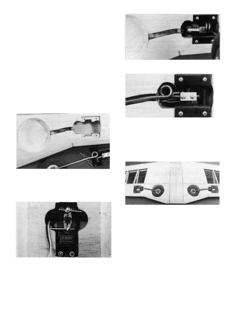
D 3. Cut out an opening in the top sheeting in the area of
the retract servo. Cut out a portion of the W-1 ribs to fit your
servo, and fabricate two 1/8" ply servo mounting rails in the
general area shown on the fuse plan side view. Install the
retract servo, and attach the pushrods to the servo by means
of EZ Connectors as shown.
D 4. Temporarily install all retract components. Test the
operation of your retracts making sure they operate freely and
reliably. Also make sure they "lock" in both the up and down
positions. In the retracted position, the LG wire should be just
inside the LE sheeting.
D 5. Blend the bottom sheeting as neatly as possible
around the retracts.
D 6. Add lightweight balsa filler inside the wheel well to
smooth any imperfections, and to fillet the joint between the
floor and the sides.
D 7. Use polyester resin or 30-minute epoxy thinned with
alcohol to fuelproof the entire retract area and wheel well
area.
D 8. When installing the landing gear covers (optional),
it may be necessary to add plywood shims between the L.G.
20