Great Planes P-51D Mustang 40 Kit - GPMA0175 User Manual
Page 19
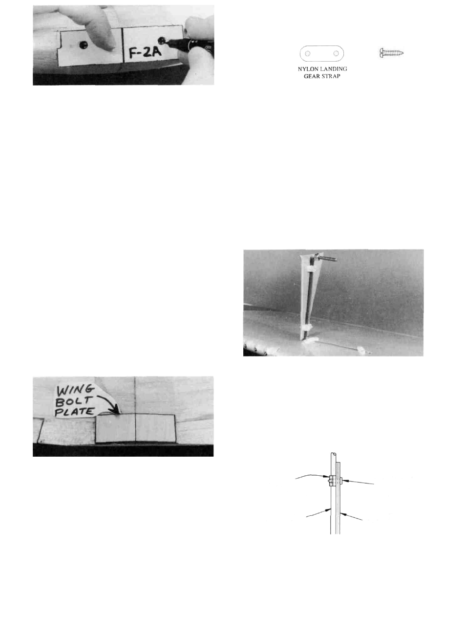
D 2. Check the plan for the location of the nylon landing
gear straps and temporarily install them, using #2 x 3/8" sheet
metal screws-
#2 X 3/8" SHEET
METAL SCREW
D 2. Holding the die-cut 1/8" ply F-2A on the leading
edge, in the exact center of the wing, mark the dowel
locations through the holes in F-2A.
D 3. Remove F-2A and double check to make sure the
dowel locations are both the same distance from the wing
center joint.
D 4. It is important that you now drill the dowel holes
accurately! To insure accurately positioned holes, begin by
drilling small (1/8") holes in the center of the marked loca-
tions. Then gradually increase drill bit sizes until you have
finally drilled the holes to 1/4" diameter. The final holes you
drill must extend at least 1-3/4" into the wing to penetrate the
inner dowel plates.
D 5. Sand one end of each wing dowel to a rounded or
pointed shape. This is the end that will be inserted. Do not
sand the other end at this time.
D 6. Trial fit the dowels into the dowel holes, and trial fit
F-2A over the dowels. If the dowels fit too tightly, you may
enlarge the holes slightly using a round file, or you may sand
the dowels down slightly. Do not glue the dowels in place at
this time.
INSTALL WING BOLT PLATE
D 1. Mark a centerline on the die-cut 1/16" x 3" x 1-1/4"
ply wing bolt plate.
D 2. Position the wing bolt plate on the bottom of the
wing, and line it up with the wing TE and centerline. Glue it
in place.
D 3. Sand the wing bolt plate flush with the wing TE.
FILL LANDING GEAR SLOTS (Fixed gear
only)
D 4. Temporarily install the main LG wires.
D 3. Using scraps of balsa, fill the ends of the slots in the
notched LG blocks and sand flush with the surface of the
wing. This will aid in covering later.
INSTALL LANDING GEAR COVERS
(Optional)
NOTE: If you arc installing a retractable landing gear,
please refer to the special instructions included in the
next section (page 20).
D 1. Find the two die-cut 1/8" ply landing gear covers,
and sand the front and rear edges to a slightly rounded shape.
D 2. Mount the L.G. covers to the main landing gear,
using the nylon "hump" straps and the #4 x 3/8" sheet metal
screws. Drill 1/8" holes in the landing gear covers, and pass
the screws through the holes, screwing them into the nylon
straps, as shown in the sketch.
Nylon
'Hump" Strap
Main LG
No. 4 x 3/8"
Sheet Metal
Screw
1/8" Ply
LG Cover
19