Great Planes P-51D Mustang 40 Kit - GPMA0175 User Manual
Page 27
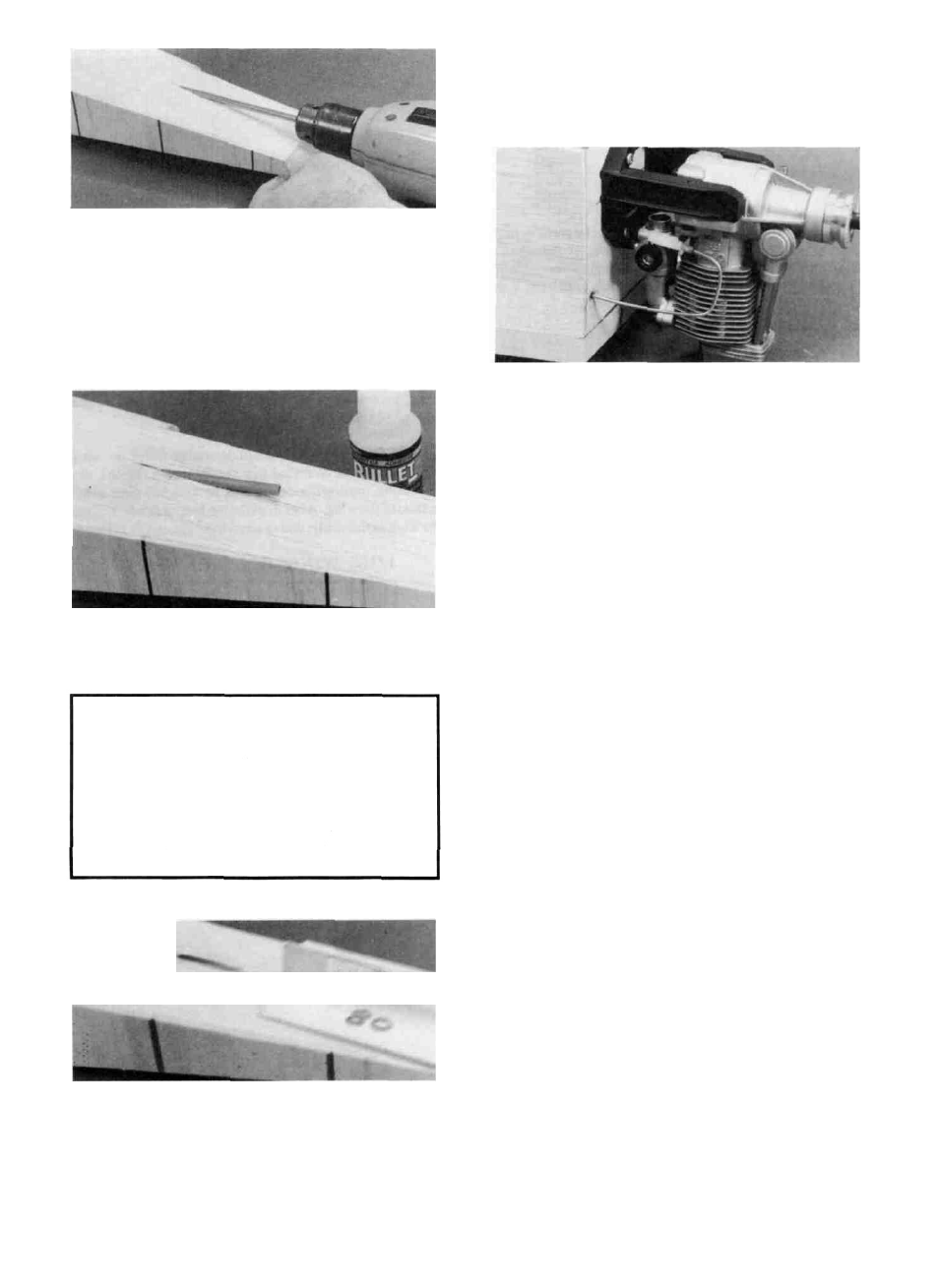
D 4. Use an Xacto knife to sharpen one end of a piece of
3/16" (outside diameter) brass tubing, then use this tubing to
cut the pushrod exit holes (you may use a 3/16" drill bit, but
the brass tube method gives a much neater cut). Determine
the location of these holes from the plans. You may chuck
this brass tube in an electric drill to aid in getting through
F-6.
D 8. Temporarily install the engine mount.
D 5. Cut one of the plastic.outer pushrod tubes in half and
insert the tubes through the holes you just cut and through
formers F-6. F-5 and F-4.
D 6. Route the pushrod tubes according to your
radio installation plan. Temporarily insert the 34"
pushrod wires into the tubes and hold them in the
correct position (with tape) at the servo end. Keep the
tubes as straight as possible. Glue the tubes to the fuse
sides at the rear exit points using thin CA glue. Use
scraps of 1/8" balsa to anchor the tubes to F-5. Do not
anchor the tubes to F-4 at this time, to allow for slight
adjustment of their positions later.
D 9. With the engine resting on the mount, plan the
throttle pushrod routing. The pushrod should be located as
close as possible to the fuse sides (to allow room for the fuel
tank), and the guide tube should not have any tight bends.
Drill a 3/16" hole in F-l for the throttle pushrod guide tube,
but stay at least 1/4" in from the outside edge of the fuse sides.
D 10. Drill or carve holes in F-2 and F-3 for the guide tube.
Use the remaining 36" plastic pushrod guide tube and trial fit
the tube in the fuselage.
D 11. Sand the plastic pushrod guide tube with 100-grit
sandpaper, then glue it in place. Trim and sand the tube flush
with the front of F-l.
D 12. Cut the pushrod wire (supplied) to the required
length, add a nylon clevis, and trial fit the throttle pushrod.
D 13. Now remove the pushrod wire, servos and engine.
MOUNT THE WING TO THE FUSE
D 1. Sand the top surface of the fuse to remove any excess
glue so the fuse will lie flat on the workbench.
D 2. Sand the entire wing saddle area lightly until the fuse
side doublers and fuse sides are flush.
D 7. Cut off the tubes at the exit points and sand them
flush with the fuse sides using a sanding block.
D 3. Insert the die-cut 1/8" ply F-2A in place against the
back of F-2 (do not glue).
D 4. Insert the 1/4" wing dowels into the wing so they
stick out only 1/8".
27