Features, Configuration – Digilent 410-138P-KIT User Manual
Page 2
Genesys Reference Manual
www.digilentinc.com
page 2 of 28
Copyright Digilent, Inc. All rights reserved. Other product and company names mentioned may be trademarks of their respective owners
Features
• Xilinx Virtex 5 LX50T FPGA, 1136-pin BGA package
• 256Mbyte DDR2 SODIMM with 64-bit wide data
• 10/100/1000 Ethernet PHY and RS-232 serial port
• multiple USB2 ports for programming, data, and hosting
• HDMI video up to 1600x1200 and 24-bit color
• AC-97 Codec with line-in, line-out, mic, and headphone
• real-time power monitors on all power rails
• 16Mbyte StrataFlash™ for configuration and data storage
• Programmable clocks up to 400MHz
• 112 I/O’s routed to expansion connectors
• GPIO includes eight LEDs, two buttons, two-axis navigation switch, eight slide switches, and a 16x2
character LCD
• ships with a 20W power supply and USB cable
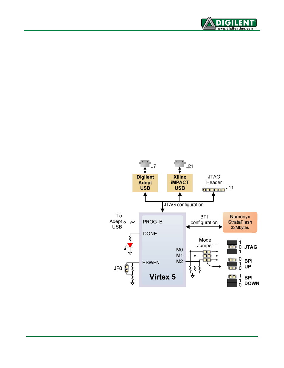
Configuration
After power-on, the FPGA on
the Genesys board must be
configured (or programmed)
before it can perform any
functions. A USB-connected
PC can configure the board
using the JTAG interface
anytime power is on, or a file
can be automatically
transferred from the
StrataFlash ROM at power-on.
An on-board "mode" jumper
selects which programming
mode will be used.
Both Digilent and Xilinx freely
distribute software that can be
used to program the FPGA and
the Flash ROM. Configuration
files stored in the ROM use the
Byte Peripheral Interface (BPI)
mode. In BPI UP mode, the
FPGA loads configuration data
from the StrataFlash in an
ascending direction starting at address 000000. In BPI DOWN mode, configuration data loads in a
descending direction starting at address 03FFFF.