Basic i/o, Character lcd – Digilent 410-138P-KIT User Manual
Page 18
Genesys Reference Manual
www.digilentinc.com
page 18 of 28
Copyright Digilent, Inc. All rights reserved. Other product and company names mentioned may be trademarks of their respective owners
The IDT clock generator chip is
JTAG programmable using
iMPACT. If users change the
factory default configuration of the
clock generator, reference designs
and automated tests might not
work as designed. The same
IDT5V9885 configuration file used
during board manufacturing is
available from the Digilent website
and it can be used to restore the
IDT default settings.
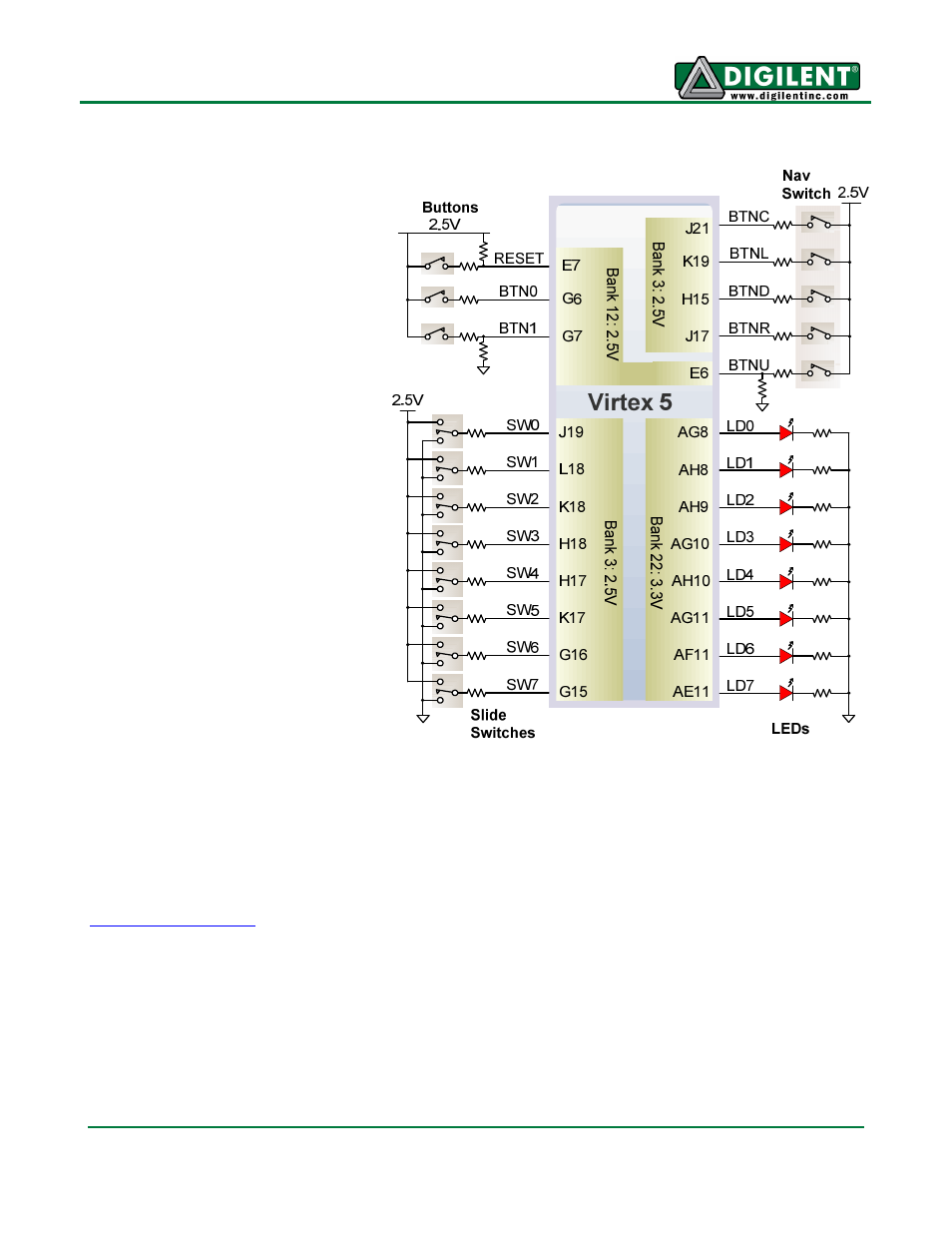
Basic I/O
Genesys includes three
pushbuttons, a navigation switch
comprised of five pushbuttons
packaged in a two-axis rocker
switch, eight slide switches, and
eight LEDs for basic digital input
and output. The buttons,
navigation switch, and slide
switches are connected to the
FPGA via series resistors to
prevent damage from short
circuits. The high efficiency LED
anodes are connected to a 3.3V
bank on the FPGA via 390-ohm
resistors, so they are illuminated
by about a 1mA current when a
logic high is placed on the
corresponding pin.
Character LCD
The Genesys board contains a standard 2x16 character LCD, typified by the Powertip 1602D (see
www.powertip.com.tw
). The display uses a Sitronix ST7066U or compatible controller. Pertinent parts
of the controller data sheet are recreated below. Please refer to the vendor data sheet for more
detailed information.
The LCD controller contains a character-generator ROM (CGROM) with 208 preset 5x8 character
patterns, a character-generator RAM (CGRAM) that can hold eight user-defined 5x8 characters, and a
display data RAM (DDRAM) that can hold 80 character codes. Character codes written into the
DDRAM serve as indexes into the CGROM (or CGRAM). Writing a character code into a particular
DDRAM location will cause the associated character to appear at the corresponding display location.
Display positions can be shifted left or right by setting a bit in the instruction register (IR). The write-
only IR directs display operations (such as clear display, shift left or right, set DDRAM address, etc).