Hardware installation, Connect the power and ground – Comtrol ES7528 User Manual
Page 9
RocketLinx ES7528 User Guide: 2000509 Rev. C
Hardware Installation - 9
Hardware Installation
You can use the following subsections to install the RocketLinx ES7528:
•
•
Connect the Digital Inputs or Relay Output
•
•
•
Connect SFP Transceivers (Combo Ports 25-28)
•
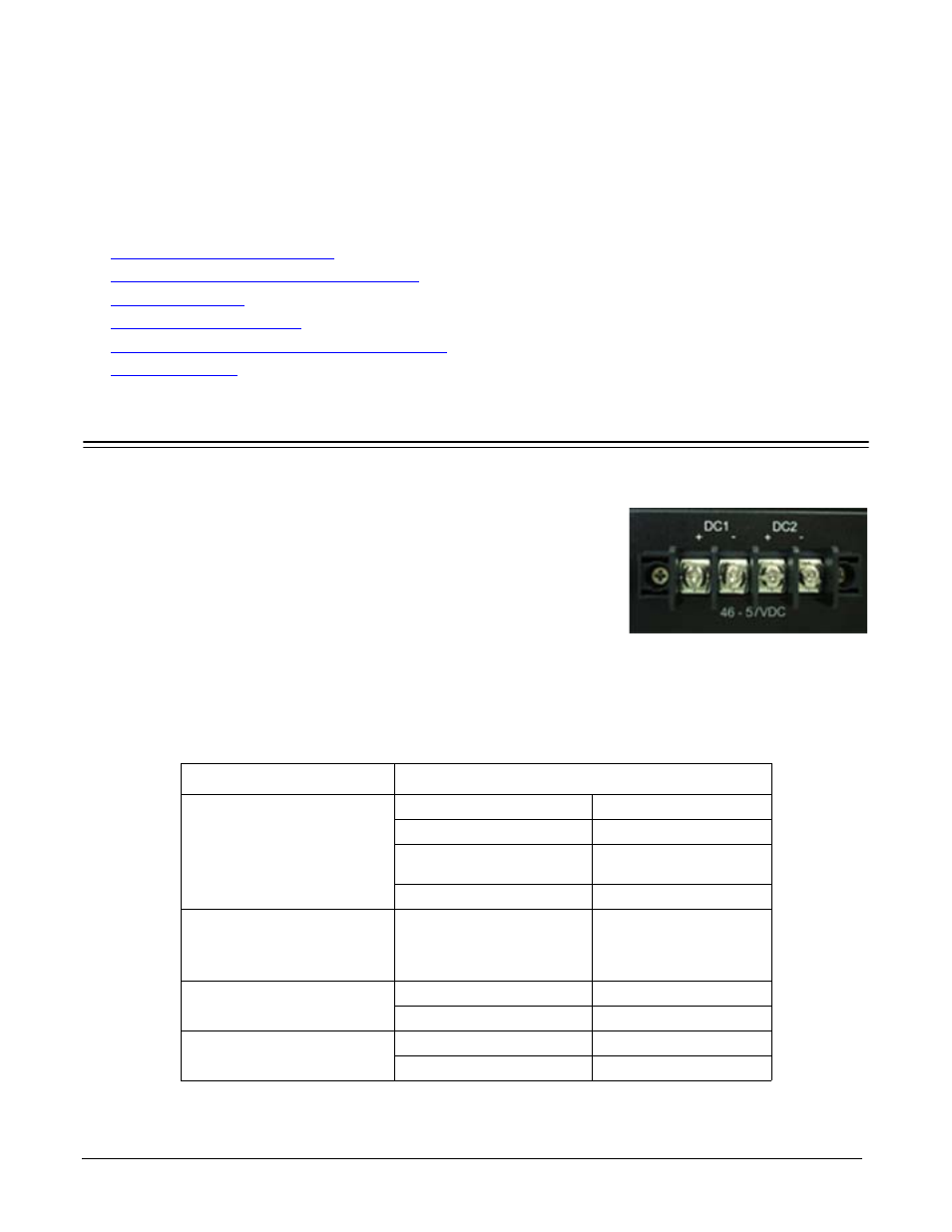
Connect the Power and Ground
You can use the following procedure to connect power and the ground to the ES7528. The ES7528 is equipped
with both AC and DC1/DC2 power inputs.
1.
Connect the power cord to the AC power input connector.
Note: To reach the maximum total power budget, power inputs must
be aggregated. Refer to the following table for detailed
information.
2.
Connect the DC power inputs.
a.
Insert positive and negative wires (12-24AWG) into the V+ and V-
contacts.
Note: Power should be disconnected from the power supply before
connecting it to the switch. Otherwise, your screw driver
blade can inadvertently short your terminal connections to
the grounded enclosure.
b.
Tighten the wire-clamp screws to prevent the wires from coming loose.
Electrical Specifications
Value
Power Input Voltage
DC1/DC2
IEEE 802.3af
48VDC (46-57VDC)
IEEE 802.3at
53VDC (50-57VDC)
AC and DC1/DC2
aggregated
53VDC 8.2A
(maximum)
DC1/DC2 aggregated
DC1=DC2†
Power Input Voltage
PSU/AC power
100-250VAC
47~63Hz
4A
PoE Output Voltage
IEEE 802.3af
44-57VDC
IEEE 802.3at
50-57VDC
PoE Power/Port
(Maximum)
IEEE 802.3af
15.4W
IEEE 802.3at
32W
Wire: 12 to 22 AWG
DC Input: 53VDC