Connect the digital inputs or relay output, Mount the es7528 – Comtrol ES7528 User Manual
Page 11
RocketLinx ES7528 User Guide: 2000509 Rev. C
Connect the Digital Inputs or Relay Output - 11
Hardware Installation
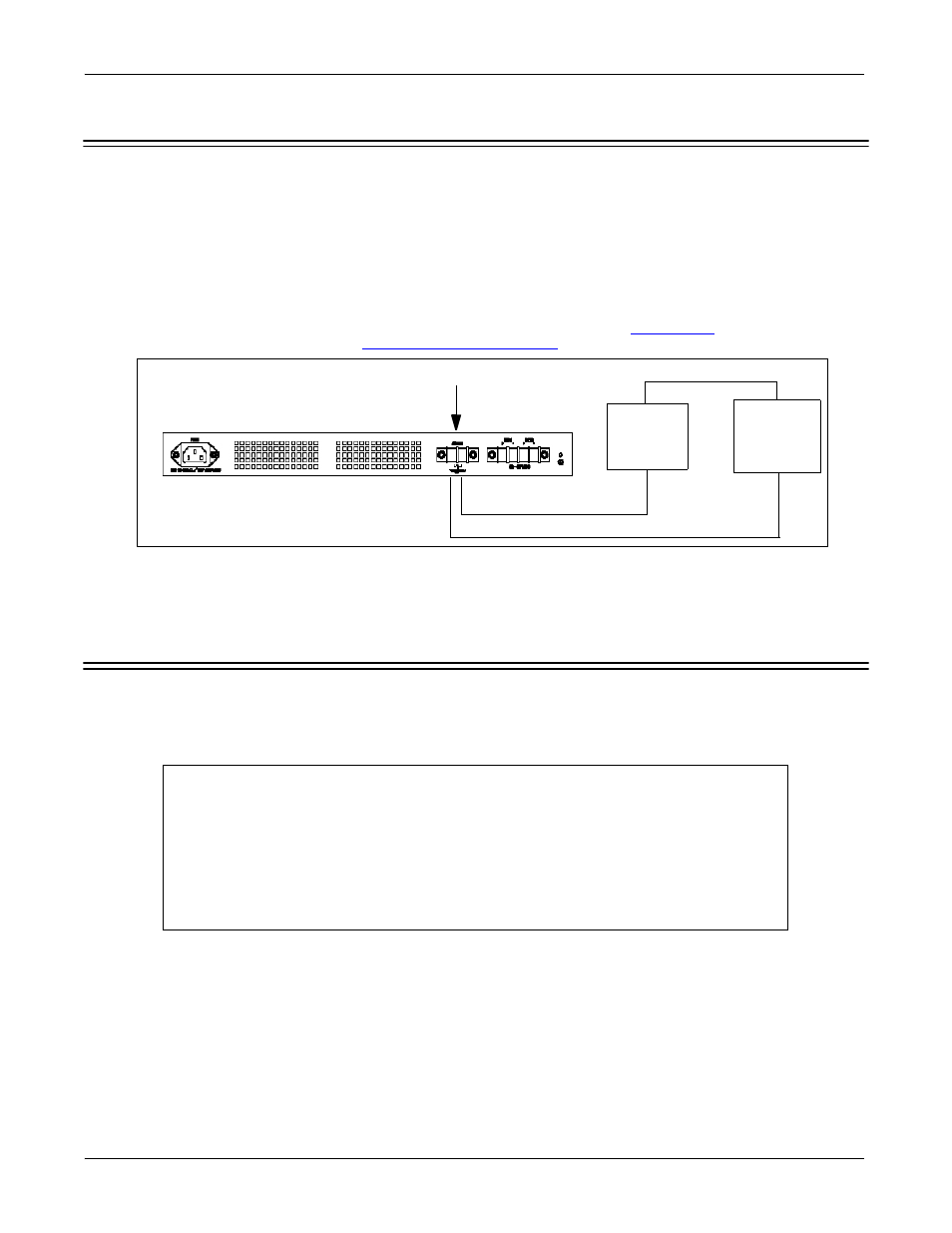
Connect the Digital Inputs or Relay Output
If desired, connect the Digital or Relay Output. The relay contacts are energized, (open) for normal operation
and close for fault conditions. The fault conditions include:
•
Dry output
•
Power failure
•
Ethernet port link break
•
Ping failure
•
Super ring failure
You can configure the fault relay settings in the ES7528 web user interface (
on Page 123) or
through the Command Line Interface (
1.
Insert the positive and negative wires (12-24 AWG) into V+ and V-.
2.
Tighten the wire-clamp screws to prevent the wires from coming loose.
Mount the ES7528
You can use the following procedure to mount the ES7528 into a rack.
1.
Attach the brackets to the ES7528 by using the screws provided in the rack mounting kit.
2.
Mount the ES7528 in a 19-inch rack by using the four rack-mounting screws provided in the kit.
Note: When installing multiple switches in high temperature environments, reserve 0.5U-1U of free space
between the switches. It is important to disperse the heat generated by the ES7528.
Wire: 12 to 22 AWG
Digital Output (Relay) 1A/24VDC
Power
Source
Alarm/
PLC Input
-
+
Ground the chassis to earth ground
Temperature: Verify that the rack environment temperature conforms to the
specified operating temperature range. If necessary, refer to the Comtrol web site for
operating temperature ranges.
Mechanical Loading: Do not place any equipment on top of the switch. In a high
vibration environment, additional rack mounting protection is necessary.
Grounding: Rack-mounted equipment should be properly grounded. On the back
panel of the ES7528, there is one earth ground screw. Loosen the earth ground screw
with a screwdriver; then tighten the screw after earth ground wire is connected.