Dc power cable connection ■ mobile operation, Dc power cable connection – Kenwood TM-261A User Manual
Page 9
Attention! The text in this document has been recognized automatically. To view the original document, you can use the "Original mode".
DC POWER CABLE CONNECTION
■ Mobile Operation
The vehicle battery must have a nominal rating of 12 V.
Never connect the transceiver to a 24 V battery. Be
sure to use a 12 V vehicle battery that has sufficient
current capacity. If the current to the transceiver is
insufficient, the Display may darken during
transmission, or transmit output power may drop
excessively.
1 Route the DC power cable supplied with the
transceiver directly to the vehicle’s battery terminals
using the shortest path from the transceiver.
•
If using a noise filter, it should be installed with an
insulator to prevent it from touching metal on the
vehicle.
•
It is not recommended to use the cigarette lighter
socket since some cigarette lighter sockets introduce
an unacceptable voltage drop.
•
If the power cable must be routed through a hole in the
vehicle chassis or body, for example in the firewall at
the front of the passenger compartment, use a rubber
grommet to protect the cable from abrasion.
Dismantle the fuse holder to pass the cable through
the firewall.
The entire length of the cable must be dressed so it is
isolated from heat and moisture.
After the cable is in place, wind heat-resistant tape
arc .nd the fuse holder to protect it from moisture.
Tie down the full run of cable.
To prevent the risk of short circuits, disconnect other
wiring from the negative (-) battery terminal before
connecting the transceiver.
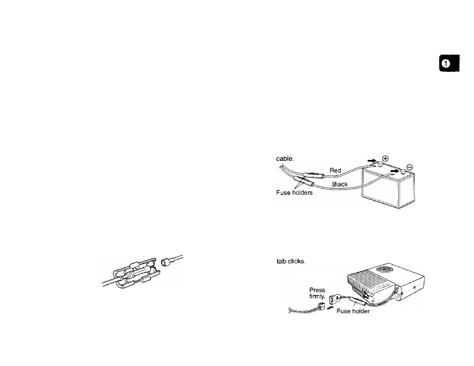
Confirm the correct polarity of the connections, and
attach the power cable to the battery terminals; red
connects to the positive (-i-) terminal, black connects
to the negative (-) terminal.
• Use the full length of the cable without cutting off
excess even if the cable is longer than required. In
particular, never remove the fuse holders from the
5
Reconnect any wiring removed from the negative
terminal.
6
Connect the DC power cable to the transceiver’s
power supply connector.
• Press the connectors firmly together until the locking