Damper wiring, Thermostat wiring – Braeburn 140404 User Manual
Page 6
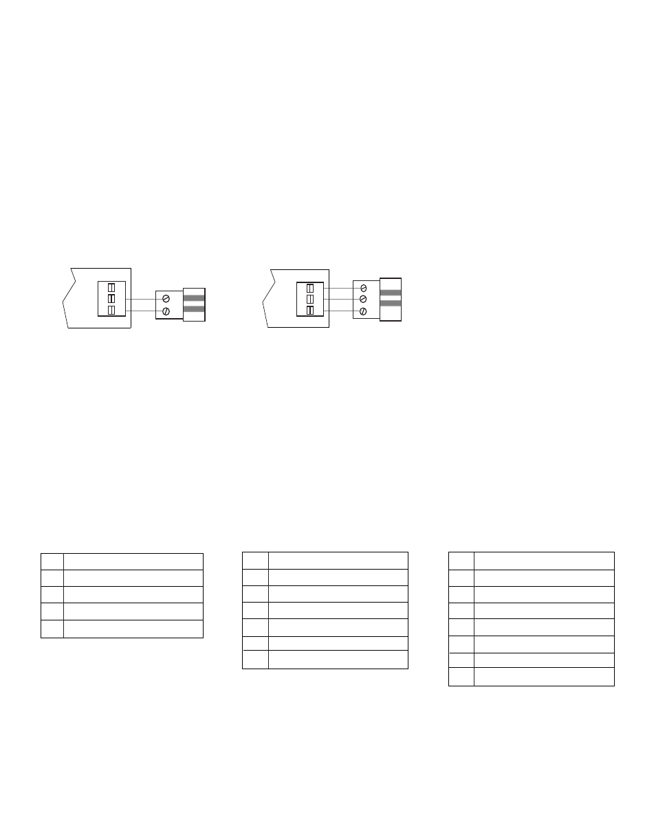
Damper Wiring
3.1
Always turn off power to the heating/air conditioning system prior to installing or adjusting the zone panel. Wire
the entire panel before applying transformer power.
Use the following general wiring instructions for all systems. Specific wiring will vary depending on the equipment
and type of system (conventional or heat pump).
Install the system dampers using the instructions provided by the manufacturer. Connect the dampers to the zone
panel as shown for either a 2-wire or 3-wire damper. The sum of all dampers powered by the zone panel should
not exceed 100 VA at 24 VAC. Use a slave relay if additional damper power is required.
ALWAYS PROVIDE DISCONNECT AND OVERLOAD PROTECTION AS REQUIRED
Max. damper VA per Zone 50 VA @ 24 VAC
M
M
PO
COM
PC
Zone Panel
2-Wire Damper
PO
C
PC
PO
COM
PC
Zone Panel
3-Wire Damper
Thermostat Wiring
3.2
Install the system thermostats using the instructions provided by the manufacturer. Connect the thermostats to
the zone panel as shown. Do not mix conventional and heat pump thermostats on the same system. You can mix
single stage and multi-stage thermostats as long as they are all conventional or heat pump.
ALWAYS PROVIDE DISCONNECT AND OVERLOAD PROTECTION AS REQUIRED
1 HEAT / 1 COOL
R 24 VAC Power
W1 Heat Call
Y1 Cooling Call
G Fan Call
C
24 VAC Transformer Common
2 HEAT / 2 COOL
R
24 VAC Power
W1 Heat Call Stage 1
W2 Heat Call Stage 2
Y1 Cooling Call Stage 1
Y2 Cooling Call Stage 2
G
Fan Call
C 24 VAC Transformer Common
CONVENTIONAL THERMOSTATS
(for use on conventional or heat pump systems)
3 HEAT / 2 COOL
R
24 VAC Power
W1 Heat Call Stage 1
W2 Heat Call Stage 2
W3 Heat Call Stage 3
Y1 Cooling Call Stage 1
Y2 Cooling Call Stage 2
G
Fan Call
C 24 VAC Transformer Common
6