Bcm modbus and address assignments, 1 bcm modbus communication & support requirements, 1 function codes – AERCO Modulex E8 Controls Guide User Manual
Page 93: 2 modbus support requirements, Gf-115-c
PR1: 02/23/12 Page 93 of 112
GF-115-C
OMM-0084_0D
AERCO International, Inc. • 100 Oritani Dr. • Blauvelt, NY 10913 • Ph: 800-526- 0288
9. BCM MODBUS AND ADDRESS ASSIGNMENTS
9.1 BCM Modbus Communication & Support Requirements
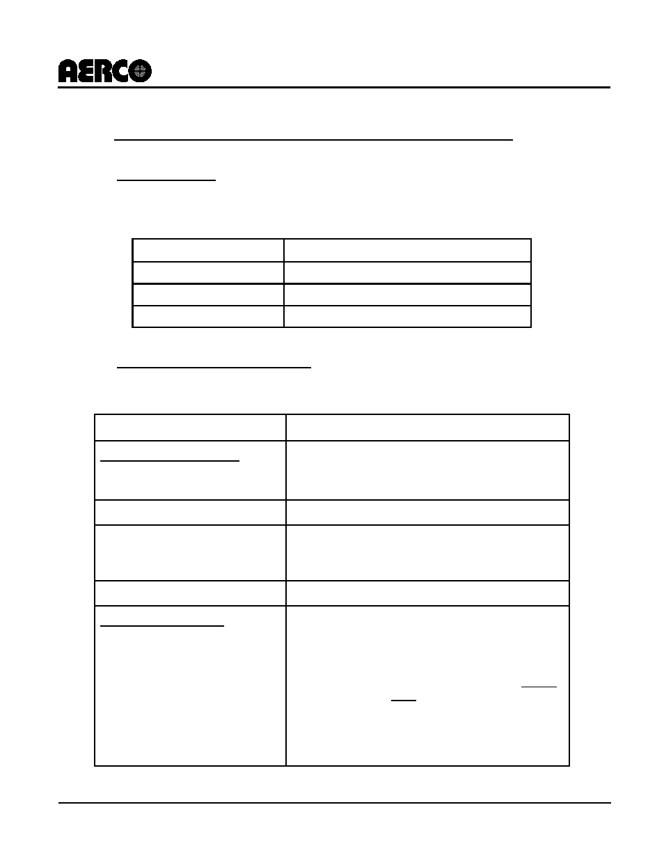
The Modbus communication support requirements incorporated in the BCM are as follows:
9.1.1 Function Codes
The BCM supports the Modbus Function Codes SHOWN IN
Table 9-1.
Table 9-1: Supported Modbus Function Codes
FUNCTION CODE
DESCRIPTION
03
Read up to 8 contiguous Holding Registers
04
Read up to 8 contiguous Address Registers
06
Write a single 16 bit Register
9.1.2 Modbus Support Requirements
The Modbus Network must conform to the support requirements listed in
Table 9-2.
Table 9-2: Modbus Support Requirements
CHARACTERISTIC
DESCRIPTION
Communication Medium
BMS II/ACS or EMS Master to
BCM Slave
RS485 2-Wire Differential Bus With Shield
RS485 Allowable Cable Length
4000 Feet Maximum
Address Support From Master
EMS
1 to 9 via Address Select Switch (SW1).
(Addresses from 10 to 127 can be implemented via
software)
Transmission Mode Support
RTU (Remote Terminal Unit)
Timing Specifications:
Baud Rate:
Data Framing:
Message Framing:
Character Framing:
Heartbeat Timeout:
Fixed at 9600
8 data bits, no parity, 1 stop bit
Silent period of at least 3.5 character times Before
first character and After last character
No more than 1.5 character times of silence
between received and transmitted characters.
Adjustable (0 or 1 – 240 seconds)