Gf-115-c, Modulex e8 controller and bcm – AERCO Modulex E8 Controls Guide User Manual
Page 100
PR1: 11/30/12
Page
100 of 112
GF-115-C
Modulex E8 Controller and BCM
Operations and Maintenance Manual
OMM-0084_0D
AERCO International, Inc. • 100 Oritani Dr. • Blauvelt, NY 10913 • Ph: 800-526- 0288
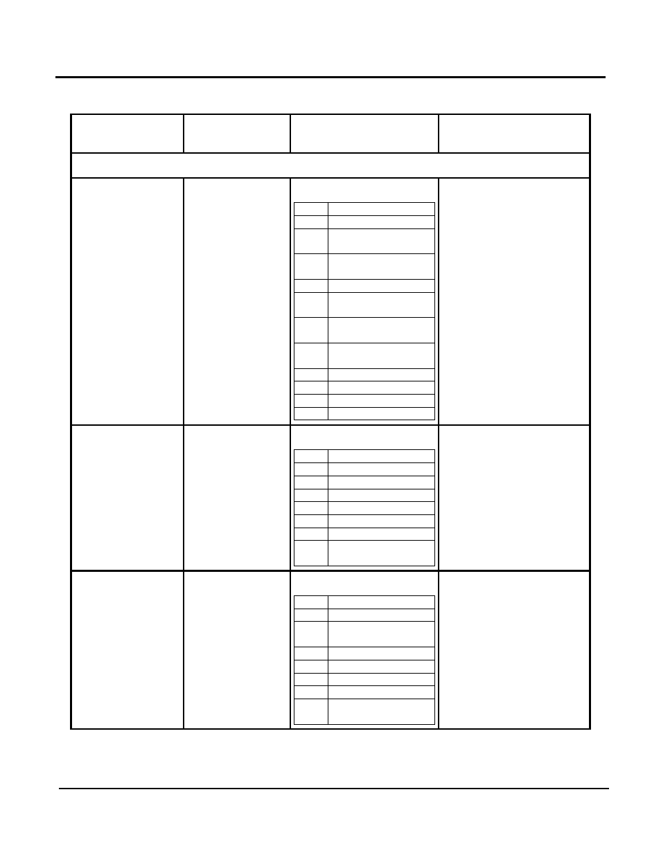
Table 9-4: BCM Standard Holding Register Address Mapping (Continued)
Modbus Data
Address
Menu Item
Units and Range
Default/(Comments)
TEST REGISTER (Continued)
3100
Digital Inputs Status
[0, 1]
Flags (0 - 0x1F80)
bit 0: eBUS RX
bit 1: eBUS-1 RX
bit 2: eBUS -1 detect (true,
false)
bit 7: Room Stat (open,
close)
bit 8: 0, not used
bit 9: RESET by Low
Voltage Detector
bit 10: RESET by clock
monitor
bit 11: RESET by Watchdog
timer
bit 12: RESET (open, close)
bit 13: SW1-1
bit 14: SW1-2
bit 15: SW1-4
(Read Only)
3101
Digital Outputs
Status [0, 1]
Flags (0 - 0x0F)
bit 0: Burner [OFF, ON]
bit 1: Pump [OFF, ON]
bit 2: Not used
Bit 3; Alarm [OFF, ON]
bit 4: DL1 [OFF, ON]
bit 5: eBUS TX
bit 6: eBUS-1 TX
bit 7: eBUS Supply [OFF,
ON]
(Read Only)
3102
Digital Output
Control in Test
Mode [0, 1]
Flags (0 - 0x0F)
bit 0: Not used
bit 1: Pump [OFF, ON]
bit 2: MPump-PWM
[100%, 0%]
bit 3; Alarm [OFF, ON]
bit 4: DL1 [OFF, ON]
bit 5: eBUS TX
bit 6: eBUS-1 TX
bit 7: eBUS Supply [OFF,
ON]
(Read/Write)