Gf-115-c, Modulex e8 controller and bcm – AERCO Modulex E8 Controls Guide User Manual
Page 35
PR1: 11/30/12
Page
35 of 112
GF-115-C
Modulex E8 Controller and BCM
Operations and Maintenance Manual
OMM-0084_0D
AERCO International, Inc. • 100 Oritani Dr. • Blauvelt, NY 10913 • Ph: 800-526- 0288
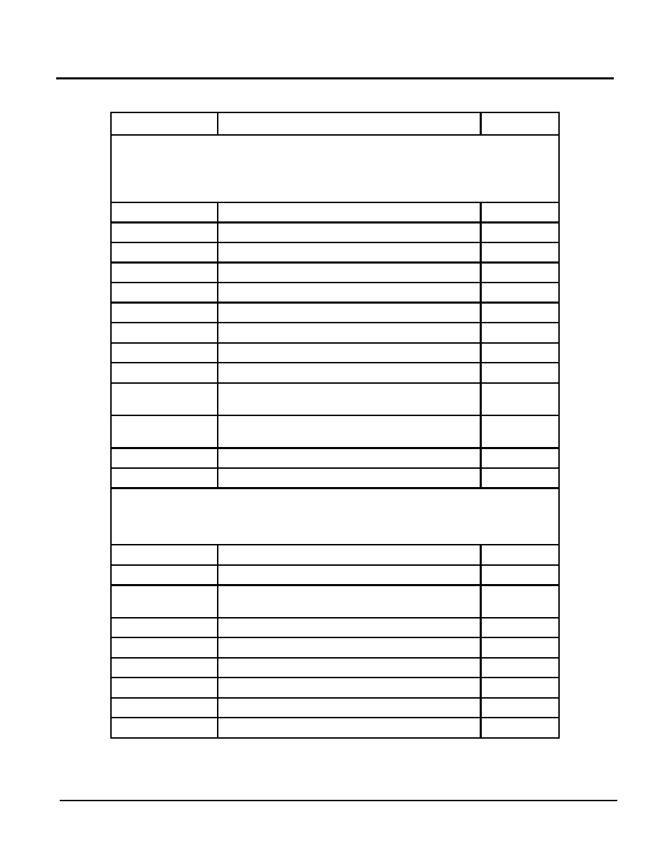
Table 4-6: SERVICE Menu Listing
FUNCTION
DESCRIPTION
REMARKS
RELAY TEST Sub-Menu
This Sub-Menu is used to check the status of the relays contained in the
Controlller. These relays are numbered 00 through 11 and are defined as shown
below. CODE NO. Entry is required to access these relays.
RELAY NO.
00
No relay
01
A1: Pump, Heating Circuit 1
02
A2: Pump, Heating Circuit 2
03
A3: Hot Water Charging Pump
04
A4: Mixer OPEN, Heating Circuit 2
05
A5: Mixer CLOSED, Heating Circuit 2
06
A6: HS 1 ON
07
A7: HS2 ON [2-stage:HS 1+2 (after 10s) ON]
08
A8: Mixer OPEN Heating Circuit 1 /
Multifunction 1
09
A9: Mixer CLOSED Heating Circuit 1 /
Multifunction 2
10
A10: Multifunction 3
11
A11: Collector Pump / Multifunction 4
SENSOR TEST Sub-Menu
This Sub-Menu is used to check and display the temperature readings of the
sensors connected to the Controller.
SENSOR
F1
Buffer storage temperature Lower
F2
Buffer storage temperature middle or room
temperature heating circuit 1
F3
Upper buffer storage temperature
F5
Flow temperature, heating circuit 2
F5
Flow temperature, heating circuit 2
F6
Upper hot water temperature
F8
Heat generator /header temperature
F9
Outside temperature