Gf-115-c, Modulex e8 controller and bcm – AERCO Modulex E8 Controls Guide User Manual
Page 30
PR1: 11/30/12
Page
30 of 112
GF-115-C
Modulex E8 Controller and BCM
Operations and Maintenance Manual
OMM-0084_0D
AERCO International, Inc. • 100 Oritani Dr. • Blauvelt, NY 10913 • Ph: 800-526- 0288
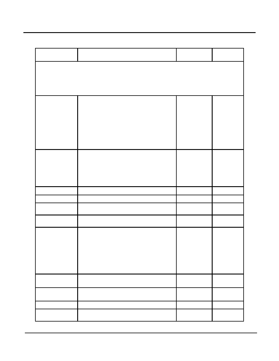
Table 4-3: EXPERT Menu Listing (Continued)
FUNCTION
DESCRIPTION
ENTRY
RANGE
DEFAULT
HEAT CIRCUIT 1 & 2 Sub-Menus
The Sub-Menu Functions for HEAT CIRCUIT 1 & HEAT CIRCUIT 2 are identical, except for
the MIXER OPEN & MIXER CLOSE Functions which apply only to HEAT CIRCUIT 1. The
Function values in this Sub-Menu level will change, depending on the Heat Circuit Function
(HC FUNCTION) selected.
HC FUNCTION
Heat Circuit Function defines type of
circuit:
00 = Standard Heat Circuit
01 = Control to fixed flow temperature
02 = Swimming pool control (HC 2
ONLY)
03 = Hot Water Circuit
04 = Return flow temp. Increase via
mixing valve.
00 – 04
00
(Standard
Heat
Circuit)
PUMP MODE
Circulation pump mode control for
ON/OFF switching of pumps.
00 = Standard pump control
01 = Pump switching per heating limits
02 = Pump switching per heating program
03 = Continuous pump operation
00 – 03
00
MIXER OPEN
Not Applicable
MIXER CLOSE
Not Applicable
MAX T-FLOW
Maximum allowable water temperature
setting for the heating circuit.
68°F – 230°F
176°F
MIN T-FLOW
Minimum allowable water temperature
setting for the heat circuit.
50°F – 230°F
50°F
T-FROST PROT
Specifies the minimum allowable outside
air temperature setting for the Frost
Protection Mode. If temperature drops
below this value, the system switches to
the Frost Protect Mode and the pumps
are switched ON.
(This Function should be set to 0°F in the
INSTALLATION Mode)
-5°F – 41°F
32°F
OUT-TEMP-
DEL
Not Applicable
N/A
N/A
SLOPE
OFFSET
Not Applicable
N/A
N/A
B-HEAT SINK
Not Applicable
N/A
N/A
RETURN
Press Program Key to exit HEAT
CIRCUIT 1 (or 2) Sub-Menu.