2 bcm fault relay, 1 bcm fault relay wiring, 2 clearing faults – AERCO Modulex E8 Controls Guide User Manual
Page 63: Gf-115-c, Modulex e8 controller and bcm
PR1: 11/30/12
Page
63 of 112
GF-115-C
Modulex E8 Controller and BCM
Operations and Maintenance Manual
OMM-0084_0D
AERCO International, Inc. • 100 Oritani Dr. • Blauvelt, NY 10913 • Ph: 800-526- 0288
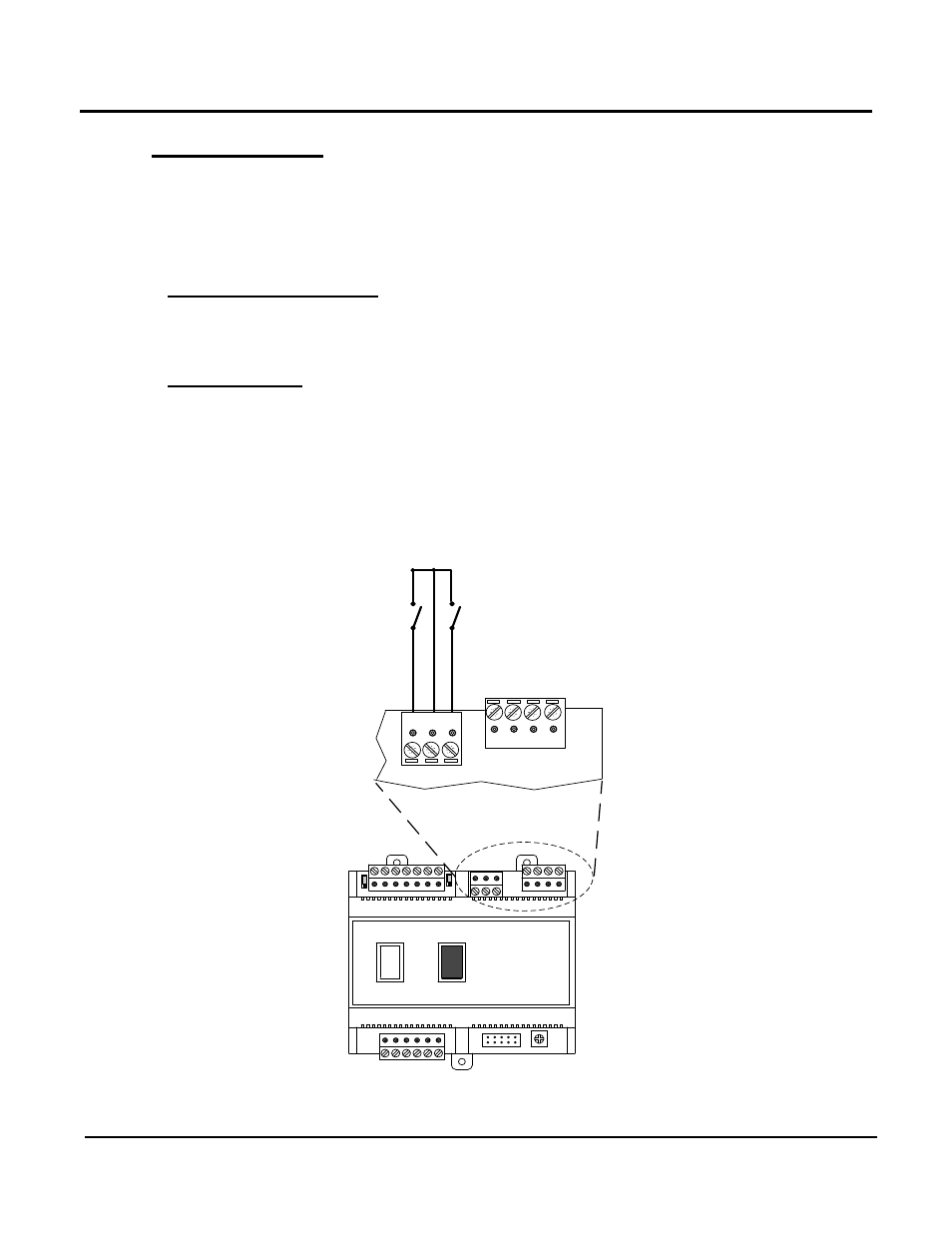
7.2 BCM Fault Relay
The BCM Fault Relay is activated (energized) when a fault condition occurs in the Modulex
Boiler. When activated, the Fault Relay provides contact closure across pins 3 and 4 of
connector Y4 on the BCM board. In addition, the red LED on the BCM board will light
continuously.
7.2.1 BCM Fault Relay Wiring
If desired, pins 3 and 4 of connector Y4 (
Figure 7-3) can be wired to an external source to
provide a remote alarm indication when the BCM Fault Relay is activated.
7.2.2 Clearing Faults
A fault can be cleared by pressing and releasing the black Reset Switch on the front cover of
the BCM. However, if the cause of the fault has not been corrected, the Fault Relay will again
be activated.
BCM
SWITCHES
4 3 2 1
3 2 1
Y4
FAULT RELAY ALARM SIGNAL
COLLECTOR CKT
.
PUMP CONTROL
RESET
ENABLE
/
DISABLE
BROWN
RED
BLACK
{
{
Y2
Y3
Y4
Y1
SW1
A1
I
0
Y3
{
Figure 7-3: BCM Fault Relay & Reset Switch Wiring