8 i/o circuits, English 3-8 i/o circuits, Chapter 3 wiring – KEYENCE SL-C Series User Manual
Page 43
Chapter 3 Wiring
3-7
3
ENGLISH
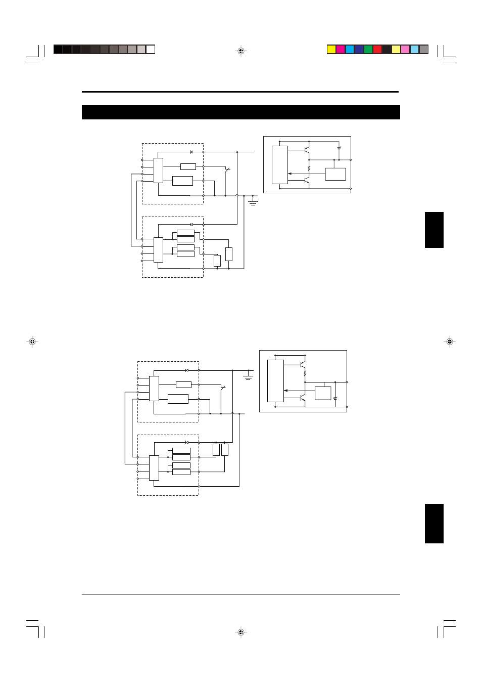
3-8 I/O Circuits
-
PNP
PNP output circuit
Main
Circuit
FSD1
FSD2
+24V
0V
Orange/Black
Main/
Sub
OSSD (PNP)
OSSD (NPN)
OSSD (PNP)
OSSD (NPN)
0V (Blue)
2.2 kΩ
Orange
Gray
Gray/Black
Brown
Purple
Pink
Blue
Brown
Black
White
Blue
OSSD1
OSSD2
Transmitter
Gray
Light interference
prevention cable input
Synchronization
cable
(Orange
/Black
)
Gray/Black
Orange
Main
Circuit
Test input
Test input
Receiver
OSSD
(PNP)
Control
circuit
OSSD
Monitor
circuit
OSSD (PNP)
Max. load 300 mA
Light interference
prevention cable output
* When test input will not be used, connect it to 0 V. If it is left disconnected, light transmission will stop.
When not using the light interference prevention connection, connect the main/sub switching input to 0 V.
Leave the light interference prevention cables disconnected after properly insulating them.
* For information about how to wire the light interference prevention cables when establishing a light inter-
ference prevention connection,
see “3-6 Connection for Light Interference Prevention (
➮page 3-5)”.
NPN
NPN output circuit
Brown
Purple
Pink
Blue
Main
Circuit
Main
Circuit
Orange
Orange
FSD1
Brown
Black
White
Blue
OSSD1
+24V
0V
OSSD
Main/
Sub
OSSD (PNP)
OSSD (NPN)
OSSD (PNP)
OSSD (NPN)
FSD2
0V(Blue)
2.2 kΩ
Gray/Black
Gray
Gray
Gray/Black
Light interference
prevention cable input
Light interference
prevention cable output
Transmitter
Receiver
Test input
Test input
OSSD
(NPN)
Contro
l circuit
OSSD
Monitor
circuit
OSSD (NPN)
Max. load 300 mA
Orange/
Black
Synchronization
cable
(Orange
/Black
)
* When test input will not be used, connect it to 0 V. If it is left disconnected, light transmission will stop.
When not using the light interference prevention connection, connect the main/sub switching input to 0 V.
Leave the light interference prevention cables disconnected after properly insulating them.
* For information about how to wire the light interference prevention cables when establishing a light inter-
ference prevention connection,
see “3-6 Connection for Light Interference Prevention (
➮page 3-5)”.