5-2 lockout status bar led indicator, 5-3 test input, English – KEYENCE SL-C Series User Manual
Page 21: Warning
Chapter 1 Overview and Specifications
1-13
1
ENGLISH
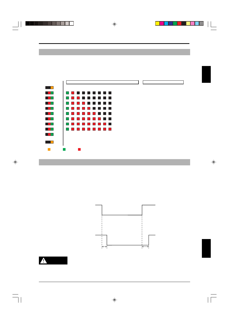
1-5-2 Lockout Status Bar LED Indicator
If the SL-C Series goes into a lockout condition, the lockout indicators on all SL-C Series units connected in
series (
➮see “Series connection” (page 3-4) for more information about in-series connection) turn ON. Also,
part of the 8-segment bar LEDs in the SL-C begins to flash, and the operator can see in what part the
trouble occurred by checking the LED flashing status in the following table. For details,
➮ see Chapter 5
“Troubleshooting” (page 5-1).
Lockout Condition Display
LOCKOUT
Orange: Control circuit anomaly
8
LEDs 1 - 8 all green:
stable, no obstructions.
8 Flashing red :
7
7 Flashing red :
6
6 Flashing red :
Communications
error
5
5 Flashing red :
4
4 Flashing red :
3
3 Flashing red :
2
2 Flashing red :
1
1 Flashing red :
SL-R11 FSD error
OSSD error
Interfering light error
SL-R11(E) error
Receiver error
Transmitter error
ON/OFF
Green: OSSD (or FSD) output is ON
Red : OSSD (or FSD) output is OFF
FUNCTION
Flashes orange when all functions have been enabled by SL-R12EX
LEDs 1 - 8 not all green:
unstable obstructions
are present.
Transmitter / Receiver
beam axes misaligned
Orange
Green
Red
Status Indicator
1-5-3 Test Input
The test input stops light beam transmission from the transmitter using an external input.
The test input is used to see if the machine connected to the SL-C can stop within the prescribed time when
the OSSD (FSD when the SL-R11 is connected to the SL-C) turns off.
For example, when test input is triggered when the SL-C is in the normal state (when OSSD or FSD output is
on when all beam axes are clear of any obstruction), the OSSD or FSD is turned off and only one bar LED of
the SL-C flashes red. (Exception is when the fixed blanking function is used.)
The test input cannot be used when the SL-R12EX is used and the Programmable Muting Bank function is
enabled. Therefore, the Programmable Muting Bank function must be canceled to enable the test input.
Test Input
ON
OFF
ON
OFF
OSSD1.2
41ms Max.
146ms Max.
Test input
WARNING
• The Test input cannot be used as an emergency stop input.
• If the SL-C Series is used as a trip device, safety-related system with restart
interlock must be established in the machine. The restart interlock must be always
available in this case.