3 when only the sl-c is used, English 3-3 when only the sl-c is used, Caution – KEYENCE SL-C Series User Manual
Page 39: Warning, Chapter 3 wiring, For pnp output
Chapter 3 Wiring
3-3
3
ENGLISH
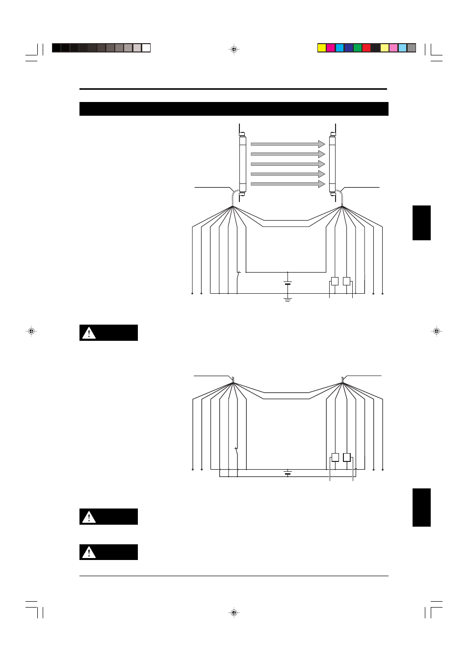
3-3 When Only the SL-C is Used
For PNP output
FSD1
FSD2
24V DC
SL-P
∗
P cable for
Transmitter/gray
Shield
Shield
Light interference prevention cable (input /-) (gray/black)*
Light interference prevention cable (output /+) (gray)*
Light interference prevention cable (input /+) (gray)*
Light interference prevention cable (output /-) (gray/black)*
0 V (blue)
0 V (Blue)
Main/sub switching input (pink)*
Test input (purple)*
OSSD2 (white)
OSSD1 (black)
+24 V (brown)
+24 V (brown)
RS-485(B) orange/black
RS-485(A) orange
Transmitter
Receiver
* When the test input will not be used, connect it to 0V. If it is left disconnected, light transmission will stop.
When not using the light interference prevention connection, connect the main/sub switching input to 0 V. Leave
the light interference prevention cables disconnected after properly insulating them.
SL-P
∗
P cable for
Receiver/black
CAUTION
PNP output shielding is connected inside the SL-C to a 0 V line. When wiring the
device, do not connect the shield wire to a +24 V wire. Doing so will cause a short
between the power supply's +24 V wire and the 0 V wire, resulting in possible
damage to the power supply or equipment.
For NPN output
FSD1
FSD2
24V DC
RS-485(B)orange/black
RS-485(A) orange
Shield
Shield
Light interference prevention cable (input /-) (gray/black)*
Light interference prevention cable (output /+) (gray)*
Light interference prevention cable (input /+) (gray)*
Light interference prevention cable (output /-) (gray/black)*
0 V (blue)
0 V (Blue)
Main/sub switching input (pink)*
Test input (purple)
OSSD2 (white)
OSSD1 (black)
+24 V (brown)
+24 V (brown)
* When the test input will not be used, connect it to 0V. If it is left disconnected, light transmission will stop.
When not using the light interference prevention connection, connect the main/sub switching input to 0 V. Leave
the light interference prevention cables disconnected after properly insulating them.
SL-P
∗
N cable for
Transmitter/gray
SL-P
∗
N cable for
Receiver/black
CAUTION
The NPN output shielding is connected inside the SL-C Series to a +24 V line.
When wiring the device, do not connect the shield wire to a 0 V wire. Doing so will
cause a short between the power supply's +24 V wire and the 0 V wire, resulting in
possible damage to the power supply or equipment.
WARNING
Synchronization cables must be shielded cable. Failure to use shielded cables may
result in significant harm to the machine operator, including serious injury or death.
Also, configure system wiring inside a metallic wiring box that has been connected
to the ground.